FUEL HYDROGEN CONTROL SYSTEM DETAILS HYDROGEN REGULATOR
CONSTRUCTION
The hydrogen regulator is installed between the hydrogen tank and the FC stack assembly, and reduces the pressure of the hydrogen coming out of the hydrogen tank. Also, it contains the medium pressure leak check port used for releasing pressure during leak checks after installing piping components, and also the relief valve provided in case the regulator malfunctions.
If the regulator malfunctions and pressure increases in the medium-pressure pipe without the pressure reduction function operating, the relief valve prevents the pressure from increasing and the medium-pressure pipe from being damaged by releasing hydrogen to the outside.

| *1 | Medium Pressure Leak Check Port | *2 | Relief Valve |

|
From Hydrogen Tank | 
|
To FC Stack |
Regulator
Using the rebound force of the internal spring, the pressure of the hydrogen gas coming from the hydrogen tank is reduced to a range of 1.0 MPa to 1.5 MPa (10.2 kg/cm2 to 15.3 kg/cm2, 145 psi to 218 psi).
When the gas pressure on the FC stack side is lower than the specified value, the spring force of the spring inside the regulator becomes greater than the gas pressure and so the spring pushes open the valve, allowing high pressure gas to flow from the hydrogen tank to the FC stack side.
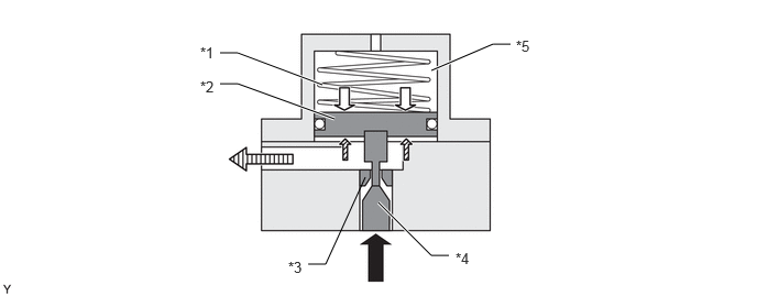
| *1 | Spring | *2 | Piston |
| *3 | Valve Seat | *4 | Valve |
| *5 | Atmospheric Pressure | - | - |
|
|
From Hydrogen Tank |
|
Spring Force |

|
Gas Pressure | 
|
To FC Stack |
When the gas pressure on the FC stack side becomes higher than the specified value, the spring force of the spring inside the regulator becomes lower than the gas pressure and so the valve closes, stopping the flow of high pressure gas.
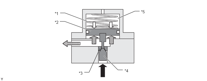
| *1 | Spring | *2 | Piston |
| *3 | Valve Seat | *4 | Valve |
| *5 | Atmospheric Pressure | - | - |
|
|
From Hydrogen Tank |
|
Spring Force |
|
|
Gas Pressure |
|
To FC Stack |
By opening and closing repeatedly, the regulator valve regulates the hydrogen gas pressure on the FC stack side.
Relief valve
If the regulator malfunctions so that the pressure reduction function does not operate, and the pressure inside the medium pressure piping has increased, hydrogen gas is vented outside by the relief valve to prevent pressure increase and destruction of the medium pressure piping.