INTAKE / EXHAUST INTAKE SYSTEM DETAILS AIR FLOW METER
CONSTRUCTION
A compact and lightweight resin silicon chip plug-in type mass air flow meter sub-assembly is used.
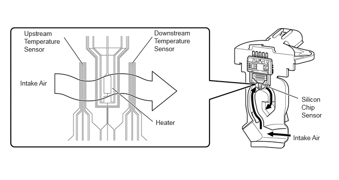
The silicon chip plug-in type mass air flow meter sub-assembly allows a portion of the intake air to flow through the detection area. By directly measuring the mass and the flow rate of the intake air, the detection precision is improved and the intake air resistance is reduced.
Intake air passes in order from the upstream temperature sensor of the silicon chip sensor in the bypass passage to the heater and then to the downstream temperature sensor. Intake air that passes through the downstream temperature sensor goes through the heater, so the temperature of the intake air rises, creating a temperature difference with the upstream sensor. The temperature difference between each of these temperature sensors changes according to the flow speed of the intake air when it passes through the silicon chip sensor. The resulting temperature difference is detected by a bridge circuit and is converted to frequency by a control circuit before it is output. The temperature difference between the upstream and downstream temperature sensors located on each side is detected with the heater, so the backward flow range with a negative temperature difference when the upstream side temperature is higher than the downstream side is also detected.
The EV control ECU calculates the intake air volume based on the frequency signal input from the mass air flow meter sub-assembly, and uses this information to determine the fuel injection time and to provide the optimal air-fuel ratio.