DOOR / HATCH LUGGAGE COMPARTMENT DOOR CLOSER SYSTEM DETAILS LUGGAGE DOOR CLOSER
CONSTRUCTION
When the luggage compartment door becomes ajar, each built-in detection switch (half switch and pawl switch) detects the ajar position and the luggage door closer motor is operated normally to fully close the luggage compartment door.
The luggage closer ECU determines the luggage compartment door courtesy output from the condition of the half switch and pawl switch.
A Hall IC, which detects the rotation position of the sector gear, is provided in the luggage door closer assembly.
The latch mechanism is mechanically connected to the luggage compartment door lock cylinder assembly or luggage compartment door inside handle by a cable. As a result, the latch mechanism can be operated by inserting and using a mechanical key or pulling the luggage compartment door inside handle.
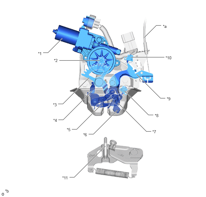
| *1 | Luggage Door Closer Motor | *2 | Pinion |
| *3 | Sector Gear | *4 | Luggage Door Lock Close Lever |
| *5 | Latch | *6 | Luggage Door Lock Ratchet Sub-assembly |
| *7 | Luggage Door Lock Lever Sub-assembly | *8 | Pawl Switch |
| *9 | Luggage Door Open Lever | *10 | Half Switch |
| *11 | Striker | - | - |
| *a | Connected to Luggage Compartment Door Lock Cylinder Assembly | *b | This illustration represents an image. |
OPERATION
Close Operation
When the luggage compartment door becomes ajar, the latch (*1 in illustration) is pushed by the striker (*4 in illustration) and rotates in the direction of the arrow (*b in illustration). At the same time, the luggage compartment door lock ratchet sub-assembly (*2 in illustration) rotates in the direction of the arrow (*c in illustration), and the pawl switch (*3 in illustration) is turned from off to on.
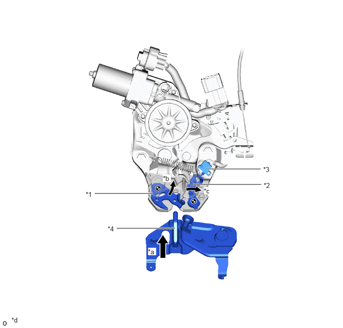
| *1 | Latch | *2 | Luggage Door Lock Ratchet Sub-assembly |
| *3 | Pawl Switch | *4 | Striker |
| *a | Striker Approach Direction | *b | Latch Rotation Direction |
| *c | Luggage Door Lock Ratchet Sub-assembly Rotation Direction | *d | This illustration represents an image. |
As the striker (*4 in illustration) moves further in the direction of the arrow (*a in illustration), the luggage compartment door open lever (*5 in illustration) rotates in the direction of the arrow (*c in illustration). This separates the luggage compartment door open lever (*5 in illustration) from the half switch (*6 in illustration), and the half switch (*6 in illustration) is turned from on to off. Then, the luggage compartment door closer motor operates normally to start a close operation.
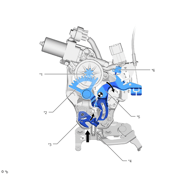
| *1 | Pinion | *2 | Sector Gear |
| *3 | Latch | *4 | Striker |
| *5 | Luggage Door Open Lever | *6 | Half Switch |
| *a | Striker Approach Direction | *b | Latch Rotation Direction |
| *c | Luggage Door Open Lever Rotation Direction | *d | This illustration represents an image. |
When the close operation rotates the pinion gear (*1 in illustration) in the direction of the arrow (*a in illustration), the luggage compartment door lock close lever (*3 in illustration) is rotated in the direction of the arrow (*c in illustration) through the sector gear (*2 in illustration), and at the same time, the latch (*4 in illustration) is also rotated in the direction of the arrow (*e in illustration) and the striker (*5 in illustration) is pulled in further. Then, when the luggage compartment door becomes fully closed and the pawl switch (*7 in illustration) is turned from on to off, the luggage compartment door closer motor operates in reverse to start a return operation.
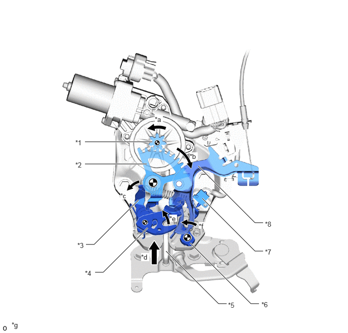
| *1 | Pinion | *2 | Sector Gear |
| *3 | Luggage Door Lock Close Lever | *4 | Latch |
| *5 | Striker | *6 | Luggage Door Lock Ratchet Sub-assembly |
| *7 | Pawl Switch | *8 | Luggage Door Open Lever |
| *a | Striker Approach Direction | *b | Latch Rotation Direction |
| *c | Luggage Door Lock Ratchet Sub-assembly Rotation Direction | *d | Pinion Rotation Direction |
| *e | Sector Gear Rotation Direction | *f | Luggage Door Lock Close Lever Rotation Direction |
| *g | This illustration represents an image. | - | - |
When the Hall IC detects the neutral position of the luggage door closer motor, the luggage door closer motor stops operating.
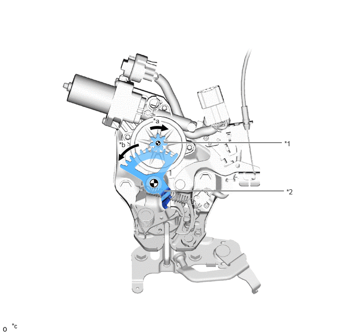
| *1 | Pinion | *2 | Sector Gear |
| *a | Pinion Rotation Direction | *b | Sector Gear Rotation Direction |
| *c | This illustration represents an image. | - | - |