ALIGNMENT / HANDLING DIAGNOSIS FRONT WHEEL ALIGNMENT ADJUSTMENT
CAUTION / NOTICE / HINT
- Necessary Procedure After Adjustment:
Replacement Part or Procedure Necessary Procedure Effects/Inoperative when not Performed Link Wheel alignment adjustment Perform "Calibration" Electronically controlled brake system malfunctions (  )
- Front Wheel Alignment:
*: Reference
Measuring Condition Unladen Tolerance Left-right Difference Front Vehicle Height (Cf - A)* 138 mm (5.43 in.) Rear Vehicle Height (Cr - B)* 56 mm (2.20 in.) Camber -0°28' (-0.46°) +/- 45' (0.75°) 45' (0.75°) or less Caster 4°29' (4.48°) +/- 45' (0.75°) 45' (0.75°) or less Steering Axis Inclination* 8°45' (8.75°) - - Toe (mm) 0 mm +/- 2 mm (0.08 in.) - Toe (°) 0° +/- 10' (0.16°) - Inside Wheel Angle 36°20' (36.33°) +/- 2° - Outside Wheel Angle 32°13' (32.22°) - -
PROCEDURE

 1. PREPARATION
Adjust the tire inflation pressure.
Bounce the vehicle about 5 times to settle the suspensions.
2.INSPECT VEHICLE HEIGHT
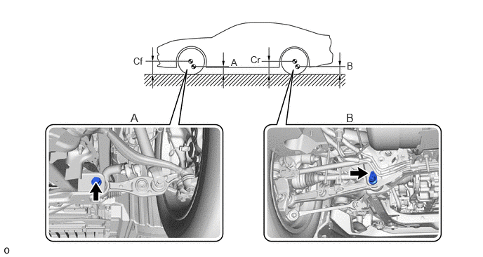
| A | Front suspension lower arm bolt center | B | Rear suspension arm attachment dent |
| Cf | Front wheel center | Cr | Rear wheel center |
3.INSPECT WHEEL ALIGNMENT
Use the wheel alignment tester or equivalent.
4.ADJUST TOE-IN

Remove the clip from the steering lack boot.
Loosen the nut of the tie rod.
Turn both steering rack ends the same amount to adjust the toe.
Hold the tie rod and tighten the nut.
- Torque:
- 88 N*m (897 kgf*cm, 65 ft.*lbf)
Fix twisted steering rack boot and install the clip with the tabs toward the front of the vehicle.
Check the tie rod is at the ball joint movable range center.
5. ELECTRONICALLY CONTROLLED BRAKE SYSTEM CALIBRATION
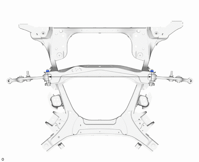
6.INSPECT FRONT SUSPENSION
Front frame assembly
- Standard:
808 mm (31.811 in.)
Front lower suspension arm assembly
- Standard:
409.2 +/- 0.46 mm (16.110 +/- 0.018 in.)

Lower No. 2 suspension arm assembly
- Standard:
310.5 +/- 0.4 mm (12.224 +/- 0.016 in.)

Front No. 1 upper suspension arm assembly
- Standard:
221.3 +/- 0.46 mm (8.713 +/- 0.018 in.)

Front No. 2 upper suspension arm assembly
- Standard:
218.4 +/- 0.46 mm (8.598 +/- 0.018 in.)