LIGHTING (INT) INTERIOR ILLUMINATION LIGHT(for Console Box) INSPECTION
PROCEDURE

 81080J
1.INSPECT NO. 1 INTERIOR ILLUMINATION LIGHT ASSEMBLY (w/o Inside Handle Illumination Light)
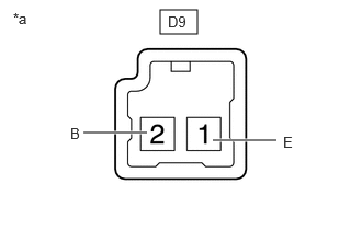
| *a | Component without harness connected
(No. 1 Interior Illumination Light Assembly) |
Check the illumination.
Apply auxiliary battery voltage to the connector and check that the light illuminate.
- OK:
Tester Connection Specified Condition Click Location & Routing(D9)Location & Routingewd_type=routing;type=c;code=D9
Click Connector(D9)Instrument Panel>Instrument Panel Wire>Cup Holder Illumination (No. 1 Interior Illumination Light Assembly)ewd_type=component;type=c;code=D9;pinno=2,1
D9-2 (B) - Auxiliary battery positive (+)
D9-1 (E) - Auxiliary battery negative (-)Illuminates
If the result is not as specified, replace the No. 1 interior illumination light assembly.
81080J
2.INSPECT NO. 1 INTERIOR ILLUMINATION LIGHT ASSEMBLY (w/ Inside Handle Illumination Light)
Check the illumination.
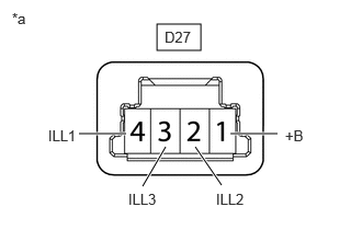
| *a | Component without harness connected
(No. 1 Interior Illumination Light Assembly) |
Apply auxiliary battery voltage to the connector and check the light illumination condition.
- OK:
Tester Connection Specified Condition Click Location & Routing(D27)Location & Routingewd_type=routing;type=c;code=D27
Click Connector(D27)Instrument Panel>Instrument Panel Wire>Cup Holder Illumination (No. 1 Interior Illumination Light Assembly)ewd_type=component;type=c;code=D27;pinno=1,2,3,4
D27-1 (+B) - Auxiliary battery positive (+)
D27-2 (ILL2) - Auxiliary battery negative (-)Red light illuminates D27-1 (+B) - Auxiliary battery positive (+)
D27-3 (ILL3) - Auxiliary battery negative (-)Green light illuminates D27-1 (+B) - Auxiliary battery positive (+)
D27-4 (ILL1) - Auxiliary battery negative (-)Blue light illuminates
If the result is not as specified, replace the No. 1 interior illumination light assembly.