RM37H0E
_58
Vehicle Interior
_095313
DOOR LOCK
_0453003
DOOR CONTROL SWITCH
G
DOOR LOCK DOOR CONTROL SWITCH INSPECTION
PROCEDURE

 84040
1.INSPECT MULTIPLEX NETWORK MASTER SWITCH ASSEMBLY
a.
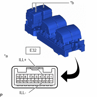
Check that the LED illuminates.
i.
0.917,1.667 1.417,1.917
0.5,0.25
1.542,2.677 1.01,2.083
true
1.021,3.281 1.563,2.885
true
2.448,0.104 1.146,0.104
1.146,0.104 1.146,0.323
true
1.271,0.115 1.271,0.427
true
1.542,0.104 1.542,0.271
true
0.146,1.896 0.458,2.094
0.313,0.198
10
false
*a
0.667,2.031 1.281,2.229
0.615,0.198
10
false
ILL+
0.688,3.198 1.302,3.396
0.615,0.198
10
false
ILL-
2.49,0.01 2.802,0.208
0.313,0.198
10
false
*b
1.052,1.698 1.51,1.896
0.458,0.198
10
false
E32
| *a | Component without harness connected
(Multiplex Network Master Switch Assembly) |
| *b | LED Illumination |
Apply auxiliary battery voltage to the multiplex network master switch assembly and check that the LED illuminates.
- OK:
Tester Connection Condition Specified Condition Click Location & Routing(E32)Location & Routingewd_type=routing;type=c;code=E32
Click Connector(E32)Body>Front Door Wire LH / Front Door Wire RH>Multiplex Network Master Switch Assemblyewd_type=component;type=c;code=E32;pinno=3,13
E32-3(ILL+) - E32-13(ILL-) E32-3(ILL+) - Auxiliary battery positive (+)
E32-13(ILL-) - Auxiliary battery negative (-)LED illuminates
If the result is not as specified, replace the multiplex network master switch assembly.