RM37H0E
_56
Audio / Visual / Telematics
_095261
NAVIGATION / MULTI INFO DISPLAY
_0447864
TOYOTA MULTI OPERATION TOUCH SYSTEM
U
NAVIGATION / MULTI INFO DISPLAY TOYOTA MULTI OPERATION TOUCH SYSTEM TERMINALS OF ECU
- HINT:
-
Check from the rear of the connector while it is connected to the components.
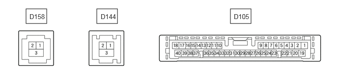
INTEGRATION CONTROL SUB-ASSEMBLY
4.885,0.188 5.323,0.5
0.438,0.313
2.052,0.188 2.49,0.5
0.438,0.313
0.552,0.188 0.99,0.5
0.438,0.313
4.958,0.271 5.417,0.469
0.458,0.198
10
false
D105
0.625,0.271 1.24,0.469
0.615,0.198
10
false
D158
2.135,0.271 2.75,0.469
0.615,0.198
10
false
D144
| Terminal No. (Symbol) | Terminal Description | Condition | Specified Condition |
|---|---|---|---|
| D105-1 (B) - D105-20 (GND) | Power source (+B) | Ignition switch off | 11 to 14 V |
| D105-3 (ACC) - D105-20 (GND) | Power source (ACC) | Ignition switch off | Below 1 V |
| Ignition switch ACC | 11 to 14 V | ||
| D105-4 (IG+) - D105-20 (GND) | Power source (IG) | Ignition switch off | Below 1 V |
| Ignition switch ON | 11 to 14 V | ||
| D105-5 (ILL+) - D105-20 (GND) | Illumination signal | Light control switch off | Light control switch in tail or head position |
| Ignition switch off
Light control switch in tail or head position |
11 to 14 V | ||
| D105-9 (ECU) - D105-20 (GND)* | Rear window sunshade operation signal | Ignition switch ON
Multi-display assembly (rear sunshade switch) pushed |
Below 1 Ω |
| Ignition switch ON
Multi-display assembly (rear sunshade switch) not pushed |
11 to 14 V | ||
| D105-17 (VMTR) - D105-20 (GND) | Visual mute signal | Ignition switch ACC
Screen display changing |
3.5 V or higher → Below 1 V → 3.5 V or higher |
| D105-18 (TX+) - D105-20 (GND) | AVC-LAN communication signal | - | - |
| D105-20 (GND) - Body ground | Ground | Always | Below 1 Ω |
| D105-31 (CANN) | CAN communication signal | - | - |
| D105-32 (CANP) | CAN communication signal | - | - |
| D105-35 (TX1-) | AVC-LAN communication signal | - | - |
| D105-36 (TX1+) | AVC-LAN communication signal | - | - |
| D105-39 (VMTI) - D105-20 (GND) | Visual mute signal | Ignition switch ACC
Screen display changing |
3.5 V or higher → Below 1 V → 3.5 V or higher |
| D105-40 (TX-) - D105-20 (GND) | AVC-LAN communication signal | - | - |
| D158-1 (GV+) | Video signal (Digital) | - | - |
| D158-2 (GV-) | Video signal (Digital) | - | - |
| D158-3 (GVG) - Body ground | Shield ground | Always | Below 1 Ω |
| D144-1 (GV+) | Video signal (Digital) | - | - |
| D144-2 (GV-) | Video signal (Digital) | - | - |
| D144-3 (GVG) - Body ground | Shield ground | Always | Below 1 Ω |
*: w/ Rear Sunshade System
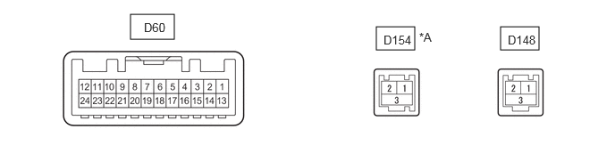
MULTI-DISPLAY ASSEMBLY
1.521,0.167 2.031,0.458
0.51,0.292
4.385,0.313 4.833,0.583
0.448,0.271
5.833,0.313 6.281,0.583
0.448,0.271
1.677,0.24 2.135,0.438
0.458,0.198
10
false
D60
4.469,0.385 5.083,0.583
0.615,0.198
10
false
D154
5.917,0.385 6.531,0.583
0.615,0.198
10
false
D148
4.885,0.354 5.5,0.552
0.615,0.198
10
false
*A
| *A | w/ Panoramic View Monitor System | - | - |
| Terminal No. (Symbol) | Terminal Description | Condition | Specified Condition |
|---|---|---|---|
| D60-2 (ILL+) - D60-13 (GND1) | Illumination signal | Ignition switch ON
Light control switch AUTO, expose the automatic light control sensor to a light |
Below 1 V |
| Ignition switch ON
Light control switch in tail or head position |
11 to 14 V | ||
| D60-7 (TX+) | AVC-LAN communication signal | - | - |
| D60-11 (VMTI) - D60-13 (GND1) | Visual mute signal | When image on display switches | 3.5 V or higher
→ Below 1 V → 3.5 V or higher |
| D60-12 (B) - D60-13 (GND1) | Power source (+B) | Ignition switch off | 11 to 14 V |
| D60-13 (GND1) - Body ground | Ground | Always | Below 1 Ω |
| D60-19 (TX-) | AVC-LAN communication signal | - | - |
| D60-24 (ACC) - D60-13 (GND1) | Power source (ACC) | Ignition switch off | Below 1 V |
| Ignition switch ACC | 11 to 14 V | ||
| D148-1 (GV+) | Video signal (Digital) | - | - |
| D148-2 (GV-) | Video signal (Digital) | - | - |
| D148-3 (GVG) | Shield ground | - | - |
RADIO RECEIVER ASSEMBLY
Click hereAudio / Visual / Telematics>NAVIGATION / MULTI INFO DISPLAY>NAVIGATION SYSTEM>TERMINALS OF ECU