Q710 HYBRID TRANSMISSION / TRANSAXLE ELECTRONIC SHIFT LEVER SYSTEM "P" Position Switch Circuit
PROCEDURE
Turn the ignition switch to ON.
Depress the brake pedal and move the shift lever to select neutral (N).
Push the P position switch (parking switch) to select park (P).
Jiggle the connectors and wire harness that connect the P position switch (parking switch) to the P1 terminal of the shift control ECU up and down, and left and right.
Check for DTCs.
- Powertrain > EV > Trouble Codes
- 50001 397
- Result:
Result Proceed to None of the DTCs are output. A Any of the DTCs are output. B
Turn the ignition switch off.
A
B
Turn the ignition switch to ON.
Jiggle the connectors and wire harness that connect the P position switch (parking switch) to the P1 terminal of the shift control ECU up and down, and left and right.
Check for diagnosis related information.
- Powertrain > EV > Utility
-
Tester Display Diagnosis Related Information - 50005 397 1056
- Result:
Result Proceed to No diagnosis related information is output. A The diagnosis related information in the table below is output. B
Diagnosis Related Information P085011 P085015
Turn the ignition switch off.
A
B
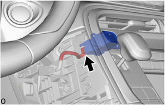
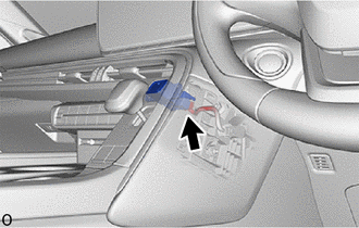
Check the connector connections and contact pressure of the relevant terminals for the P position switch (parking switch) connector.
- OK:
The connector is connected securely and there are no contact pressure problems.
- Result:
Proceed to OK NG
OK
NG
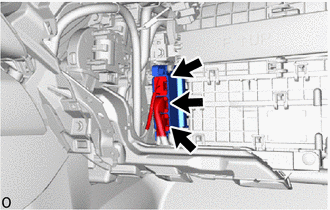
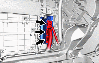
Check the connector connections and contact pressure of the relevant terminals for the shift control ECU connectors.
- OK:
The connectors are connected securely and there are no contact pressure problems.
- Result:
Proceed to OK NG
OK
NG
Disconnect the D93 shift control ECU connector.
Disconnect the D17 P position switch (parking switch) connector.
Measure the resistance according to the value(s) in the table below.
- Standard Resistance (Check for Open):
Tester Connection Condition Specified Condition Click Location & Routing(D93,D17)Location & Routingewd_type=routing;type=c,c;code=D93,D17
Click Connector(D93)Instrument Panel>Instrument Panel Wire>Shift Control ECUewd_type=component;type=c;code=D93;pinno=10
Click Connector(D17)Instrument Panel>Instrument Panel Wire>Parking Switchewd_type=component;type=c;code=D17;pinno=2
D93-10 (P1) - D17-2 (S) Always Below 1 Ω
- Standard Resistance (Check for Short):
Tester Connection Condition Specified Condition Click Location & Routing(D93,D17)Location & Routingewd_type=routing;type=c,c;code=D93,D17
Click Connector(D93)Instrument Panel>Instrument Panel Wire>Shift Control ECUewd_type=component;type=c;code=D93;pinno=10
Click Connector(D17)Instrument Panel>Instrument Panel Wire>Parking Switchewd_type=component;type=c;code=D17;pinno=2
D93-10 (P1) or D17-2 (S) - Body ground and other terminals Always 10 kΩ or higher
Reconnect the D17 P position switch (parking switch) connector.
Reconnect the D93 shift control ECU connector.
- Result:
Proceed to OK NG
OK
NG