RM37H0E
_58
Vehicle Interior
_094007
POWER OUTLETS (INT)
_0454981
WIRELESS CHARGING SYSTEM
J
POWER OUTLETS (INT) WIRELESS CHARGING SYSTEM Wireless Charger Illumination Circuit
DESCRIPTION
When the taillight is on, this circuit sends an illumination signal to the mobile wireless charger cradle assembly.
WIRING DIAGRAM
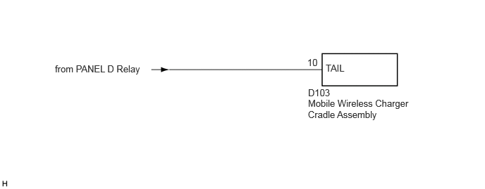
0.813,0.938 2.198,1.167
1.385,0.229
10
false
from PANEL D Relay
4.813,0.927 5.229,1.104
0.417,0.177
10
false
TAIL
4.542,0.844 4.771,1.021
0.229,0.177
10
false
10
4.552,1.448 6.094,1.854
1.542,0.406
10
false
Mobile Wireless Charger Cradle Assembly
4.552,1.292 4.927,1.469
0.375,0.177
10
false
D103
PROCEDURE
1.CHECK HARNESS AND CONNECTOR (ILLUMINATION SIGNAL)
a.
Disconnect the D103 mobile wireless charger cradle assembly connector.
b.
Measure the voltage according to the value(s) in the table below.
- Standard Voltage:
Tester Connection Condition Specified Condition Click Location & Routing(D103)Location & Routingewd_type=routing;type=c;code=D103
Click Connector(D103)Instrument Panel>Instrument Panel Wire>Mobile Wireless Charger Cradle Assemblyewd_type=component;type=c;code=D103;pinno=10
D103-10 (TAIL) - Body ground Ignition switch ON, light control switch off Below 1 V Ignition switch ON, light control switch TAIL 11 to 14 V
- Result:
Proceed to OK NG
OK
PROCEED TO NEXT SUSPECTED AREA SHOWN IN PROBLEM SYMPTOMS TABLE
NG
REPAIR OR REPLACE HARNESS OR CONNECTOR