AUDIO / VIDEO AUDIO AND VISUAL SYSTEM Radio Receiver Power Source Circuit
DESCRIPTION
This is the power source circuit to operate the radio and display receiver assembly.
WIRING DIAGRAM
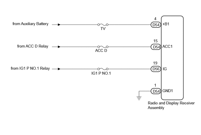
CAUTION / NOTICE / HINT
- NOTICE:
-
Inspect the fuses for circuits related to this system before performing the following procedure.
PROCEDURE
Disconnect the D54 and D56 radio and display receiver assembly connectors.
Measure the resistance according to the value(s) in the table below.
- Standard Resistance:
Tester Connection Condition Specified Condition Click Location & Routing(D54)Location & Routingewd_type=routing;type=c;code=D54
Click Connector(D54)Instrument Panel>Instrument Panel Wire>Radio Receiver Assemblyewd_type=component;type=c;code=D54;pinno=1
D54-1 (GND1) - Body ground Always Below 1 Ω
Measure the voltage according to the value(s) in the table below.
- Standard Voltage:
Tester Connection Switch Condition Specified Condition Click Location & Routing(D54,D56)Location & Routingewd_type=routing;type=c,c;code=D54,D56
Click Connector(D54)Instrument Panel>Instrument Panel Wire>Radio Receiver Assemblyewd_type=component;type=c;code=D54;pinno=4,1,15
Click Connector(D56)Instrument Panel>Instrument Panel Wire>Radio Receiver Assemblyewd_type=component;type=c;code=D56;pinno=19
D54-4 (+B1) - D54-1 (GND1) Ignition switch off 11 to 14 V D54-15 (ACC1) - D54-1 (GND1) Ignition switch ACC 11 to 14 V D56-19 (IG) - D54-1 (GND1) Ignition switch ON 11 to 14 V
- Result:
Proceed to OK NG
OK
NG