FUEL FUEL SYSTEM DISPOSAL
CAUTION / NOTICE / HINT
- CAUTION:
- ·
Do not perform the procedures within 8 meters of any ignition sources. (A distance of 10 meters or more is recommended.)
·Before performing this procedure for the hydrogen tank assembly, make sure to discharge the compressed hydrogen gas from the medium-pressure port (hydrogen supply regulator assembly) and that the pressure inside the hydrogen tank assembly is approximately 0.8 MPa (8.2 kgf/cm2).
·Because the hydrogen tank assembly is extremely heavy, be sure to perform these procedures with 2 people or more.
·Perform the procedures outdoors in a well-ventilated area.
PROCEDURE

 1.DISPOSE OF HYDROGEN TANK ASSEMBLY
- CAUTION:
- ·
To prevent static electricity, spray water on the hydrogen tank assembly and around the work area.
·Before performing work procedures, touch a metal object in contact with the ground in order to discharge any static electricity from your body.
·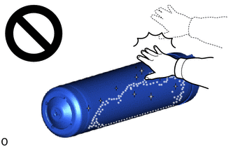
While releasing compressed hydrogen gas, the temperature inside the tank decreases and frost may form on the outside. Do not touch tanks when frost has formed on them.
·Touching tanks on which frost has formed could result in burn-like injuries due to frostbite.
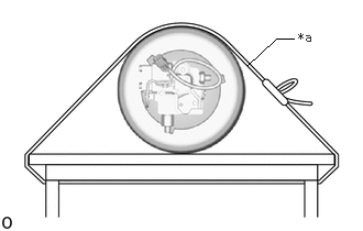
| *a | Belt |
Secure the hydrogen tank assembly to the work table with the belt in the orientation shown in the illustration.
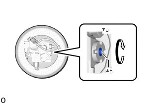
| *a | Manual Valve Closed |
| *b | Adjustment Bolt |
Using an 8 mm socket hexagon wrench, apply the specified torque to the adjustment bolt, and check that the manual valve is closed.
- Torque:
- 25 N*m (255 kgf*cm, 18 ft.*lbf)
- NOTICE:
-
Rotate the manual valve adjustment bolt, taking care not to damage the hexagonal portion. Do not damage the hexagonal portion of the adjustment bolt as the manual valve is the part that cuts off the pressure from the hydrogen tank assembly, and this would make it difficult to discharge compressed hydrogen gas from the hydrogen tank assembly.
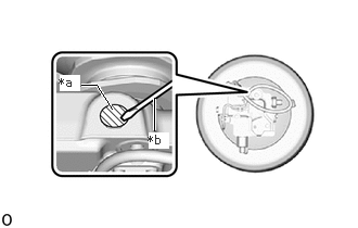
| *a | Resin |
| *b | Screwdriver |
Using a screwdriver, remove the resin around the release valve of the hydrogen tank assembly.
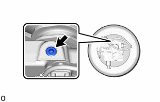
Using an 8 mm socket hexagon wrench, slowly loosen the release valve of the hydrogen tank valve assembly to discharge the compressed hydrogen gas.
- NOTICE:
- ·
The compressed hydrogen gas left in the hydrogen tank valve assembly will be discharged, so slowly loosen until no more compressed hydrogen gas comes out.
·If compressed hydrogen gas continues to be discharged, close the release valve of the hydrogen tank valve assembly and reconfirm that the manual valve of the hydrogen tank assembly is closed.
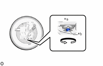
| *a | Manual Valve Open |
| *b | Adjustment Bolt |
Using an 8 mm socket hexagon wrench, slowly rotate the adjustment bolt counterclockwise to open the manual valve of the hydrogen tank assembly until compressed hydrogen gas is no longer discharged.
- NOTICE:
- ·
Rotate the manual valve adjustment bolt, taking care not to damage the hexagonal portion. Do not damage the hexagonal portion of the adjustment bolt as the manual valve is the part that cuts off the pressure from the hydrogen tank assembly, and this would make it difficult to discharge compressed hydrogen gas from the hydrogen tank assembly.
·Do not rotate the adjustment bolt 4 or more turns, as this may damage the manual valve.
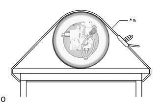
| *a | Belt |
Secure the hydrogen tank assembly with the belt in the orientation shown in the illustration.
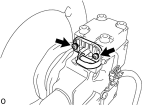
Using a T20 "TORX" socket wrench, disconnect the 2 screws and disconnect the wire harness from the hydrogen tank valve assembly.
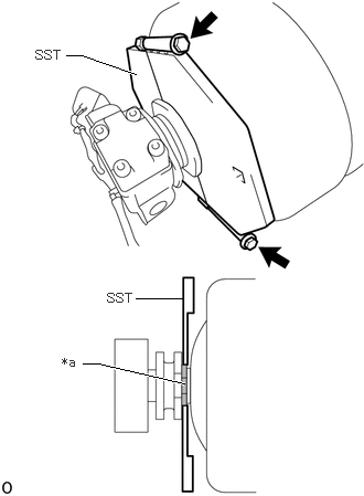
| *a | SST Installation Area |
Using a 13 mm socket wrench, install SST (hydrogen tank holding tool) to the hydrogen tank valve assembly.
- SST
- 09403-62021 (09403-00010)
- Torque:
- 28 N*m (286 kgf*cm, 21 ft.*lbf)
Remove the hydrogen tank valve assembly.
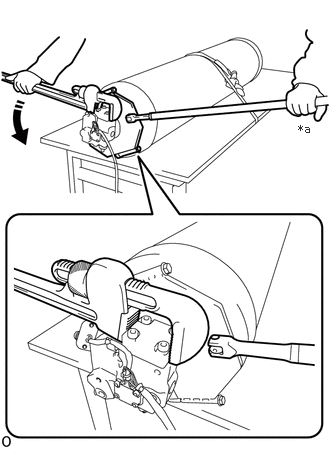
| *a | Hold |

|
Turn |
While holding SST (hydrogen tank holding tool), rotate the hydrogen tank valve assembly to loosen the valve.
- Tightening torque (reference):
- Hydrogen tank valve assembly:
485 N*m (4946 kgf*cm, 358 ft.*lbf)
- CAUTION:
-
Because the tightening torque of the hydrogen tank valve assembly is extremely high, perform this operation with 2 people.
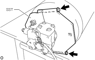
Remove SST (hydrogen tank holding tool) from the hydrogen tank valve assembly.
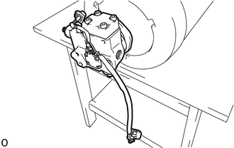
Remove the hydrogen tank valve assembly.
Remove the hydrogen tank assembly from the work table.
Soak the interior of the hydrogen tank assembly with water.
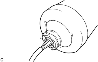
Spray water into the hydrogen tank assembly through the valve installation hole as shown in the illustration.
- NOTICE:
-
To prevent static electricity from being generated when blowing compressed air into the hydrogen tank assembly through the valve installation hole, make sure to perform this procedure.
- HINT:
-
Water filling amount: Approximately 10 liters (10.6 US qts, 8.8 Imp. qts).
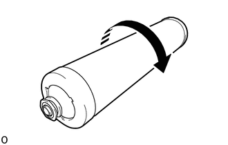
| *a | Rotate |
Rotate the hydrogen tank assembly 1 or more times so that the water is completely spread throughout the inside of the hydrogen tank assembly.
- NOTICE:
-
To prevent static electricity from being generated when blowing compressed air into the hydrogen tank assembly through the valve installation hole, make sure to perform this procedure.
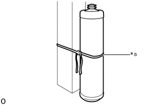
| *a | Belt |
Use a belt to secure the hydrogen tank assembly vertically.
- CAUTION:
-
Because the hydrogen tank assembly is extremely heavy, be sure to perform these procedures with 2 people or more.
- NOTICE:
-
To prevent the hydrogen tank assembly from falling over, use a belt to secure the hydrogen tank assembly.
Measure the hydrogen gas concentration.
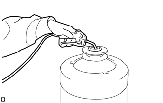
Before measuring the hydrogen gas concentration, blow compressed air into the hydrogen tank assembly through the hydrogen tank valve installation hole.
- HINT:
-
Perform in order to force out hydrogen gas that may remain in the hydrogen tank assembly and release it into the atmosphere.
If there are any water droplets, etc. adhering to the measurement locations, wipe them away before measuring the hydrogen gas concentration.
- NOTICE:
-
Performing the measurement while any water droplets, etc. are adhering could damage the hydrogen gas detector.
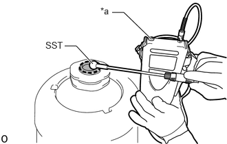
| *a | Hydrogen Gas Detector |

|
Hydrogen Concentration Measurement Area |
Using SST and a hydrogen gas detector, measure the hydrogen gas concentration at the location shown in the illustration.
- SST
- 09401-62020
- Specified value:
Less than 500 ppm
- HINT:
- ·
If the hydrogen tank assembly is left standing vertically for approximately 1 day, the hydrogen concentration becomes 500 ppm or less. (Make sure to leave it in an area with good ventilation for at least 8 hours.)
·Immediately after the measurement starts, the measured value may be unstable.
·Measure the gas concentration for approximately 10 seconds continuously.
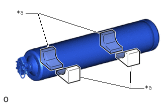
| *a | Wheel Chocks |
Place the hydrogen tank assembly on wheel chocks or similar.
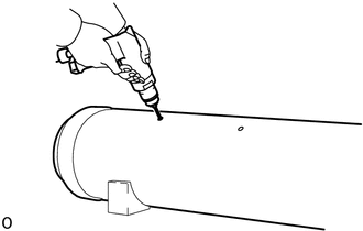
Using a drill, open 2 or more holes on the hydrogen tank assembly.
- Hole diameter:
12.5 mm (0.492 in.) or more
- CAUTION:
- ·
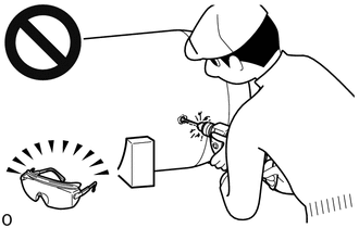
Make sure to wear protective glasses when drilling the holes.
·Drilling the holes without wearing protective glasses could result in a serious accident.
- HINT:
-
Perform this procedure so that the hydrogen tank assembly is not reused.
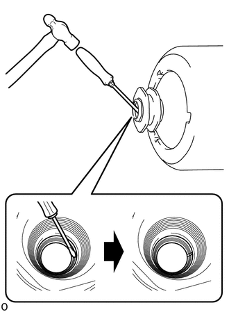
Destroy the threads of the valve installation hole of the hydrogen tank assembly as shown in the illustration.
- HINT:
-
Perform this procedure so that the hydrogen tank assembly is not reused.
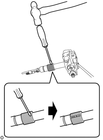
Destroy the threads of the valve of the hydrogen tank assembly as shown in the illustration.
- HINT:
-
Perform this procedure so that the hydrogen tank valve assembly is not reused.