FC CONTROL FC CONTROL SYSTEM P1D1C16 FC Converter Output Voltage Sensor Circuit Voltage Below Threshold P1D1C17 FC Converter Output Voltage Sensor Circuit Voltage Above Threshold
DESCRIPTION
The FC converter assembly consists of the 4 phase reactors and power transistor (MOSFET). It boosts the voltage output from the FC stack by operating the power transistor based on the output request value which is sent from the EV control ECU, and then outputs the boosted voltage to the inverter with converter assembly.
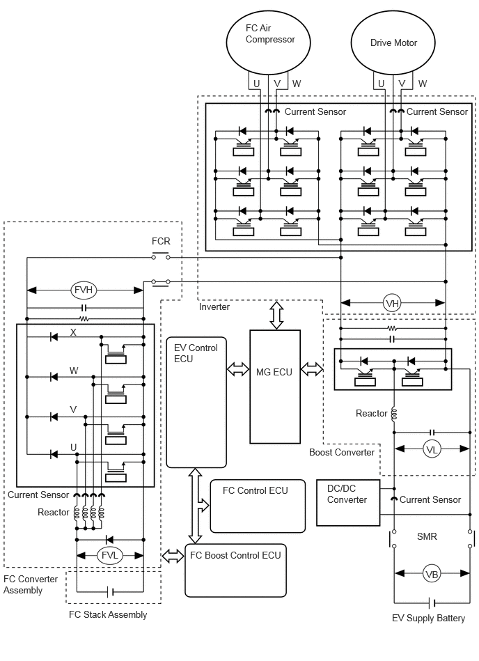
The FC boost control ECU detects high voltage after boosting (FVH) using the FC converter voltage sensor which is located inside the FC converter assembly and controls voltage boosting.
The FC converter voltage sensor changes its output voltage between 0 to 5 V, in accordance with changes in the high voltage (FVH).
The FC boost control ECU monitors the FC converter voltage sensor and detects malfunctions.
| DTC No. | Detection Item | DTC Detection Condition | Trouble Area | Warning Indicate | DTC Output from | Priority |
|---|---|---|---|---|---|---|
| P1D1C16 | FC Converter Output Voltage Sensor Circuit Voltage Below Threshold | Voltage sensor (FVH) malfunction
FC boost converter output voltage AD value is less than 0.72 V for 0.1 seconds or more continuously (1 trip detection logic) |
·
FC boost control ECU ·
FC stack main relay (FRB) ·
FC stack main relay (FRG) ·
FC precharge junction assembly (FRP) ·
ECU wire sub-assembly ·
No. 1 FC converter wire ·
No. 2 FC converter wire |
Master Warning: Comes on | FCDC | A |
| P1D1C17 | FC Converter Output Voltage Sensor Circuit Voltage Above Threshold | Voltage sensor (FVH) malfunction
FC boost converter output voltage AD value is 4.54 V or more for 0.1 seconds or more continuously (1 trip detection logic) |
·
FC boost control ECU ·
FC stack main relay (FRB) ·
FC stack main relay (FRG) ·
FC precharge junction assembly (FRP) ·
ECU wire sub-assembly ·
No. 1 FC converter wire ·
No. 2 FC converter wire |
Master Warning: Comes on | FCDC | A |
- HINT:
-
This is the DTC for failure of the FVH voltage sensor.
| DTC No. | Data List |
|---|---|
| P1D1C16 | ·
FC Voltage ·
FC Converter Output Voltage |
| P1D1C17 | FC Converter Output Voltage |
CAUTION / NOTICE / HINT
- NOTICE:
- ·
This vehicle performs FC system shutdown process after turning the ignition switch off from ON (READY). Therefore, after the ignition switch is turned off from ON (READY), do not perform any work on the electrical system for at least 10 minutes including removing connectors or disconnecting the negative (-) auxiliary battery terminal.
·When the EV control ECU determines that the temperature of FC system components is below 0°C (32°F) when the vehicle is parked with the ignition switch off, it operates the FC air compressor, hydrogen pump and FC cooling water pump for a maximum of 180 seconds to drain the FC stack assembly. When performing inspection or repairs with the ignition switch off (not ON or ON (READY)), disconnect the cable from the negative (-) auxiliary battery terminal before performing work. (If the auxiliary battery voltage is needed to conduct inspection, perform the inspection in an environment with an ambient temperature of 10°C (50°F) or higher.)
- HINT:
-
After the repair, clear the DTCs and perform the following procedure to check that DTCs are not output.
Turn the ignition switch to ON (READY) and wait for 5 seconds or more.
PROCEDURE
Replace the FC converter and FC stack assembly components listed below.
- HINT:
-
Click hereEngine / Hybrid System>FC CONTROL>CONVERTER ASSEMBLY>REMOVAL
FC boost control ECU
FC stack main relay (FRB)
FC stack main relay (FRG)
FC precharge junction assembly (FRP)
ECU wire sub-assembly
No. 1 FC converter wire
No. 2 FC converter wire
- HINT:
- ·
Refer to the parts location for the FC converter and FC stack assembly components.
Click hereEngine / Hybrid System>FC CONTROL>FC CONTROL SYSTEM>PARTS LOCATION
·Refer to the system description for the parts location of the FC converter and FC stack assembly components.
Click hereEngine / Hybrid System>FC CONTROL>FC CONTROL SYSTEM>SYSTEM DESCRIPTION
- Result:
Proceed to NEXT
NEXT