HEATING / AIR CONDITIONING AIR CONDITIONING SYSTEM B14AB Heating Three-way Valve Circuit
DESCRIPTION
The electromagnetic valve of the three-way valve is opened and closed according to air conditioning amplifier assembly control, changing the FC coolant flow modes (Independent / Intermediate / Linked).
| DTC No. | Detection Item | DTC Detection Condition | Trouble Area | Memory | DTC Output from | Priority |
|---|---|---|---|---|---|---|
| B14AB | Heating Three-way Valve Circuit | Diagnosis condition:
three-way valve operation Malfunction status:
Heating 3-way valve operation request signal is output, but the actual position information of the heating three-way valve has not reached the target position Detection time:
Continuously for 10 seconds or more |
·
Three-way valve ·
Harness or connector ·
Air conditioning amplifier assembly |
Memorized | Air Conditioner | A |
- HINT:
-
The air conditioning amplifier assembly stores this DTC if the malfunction has occurred for the period of time indicated in the parentheses.
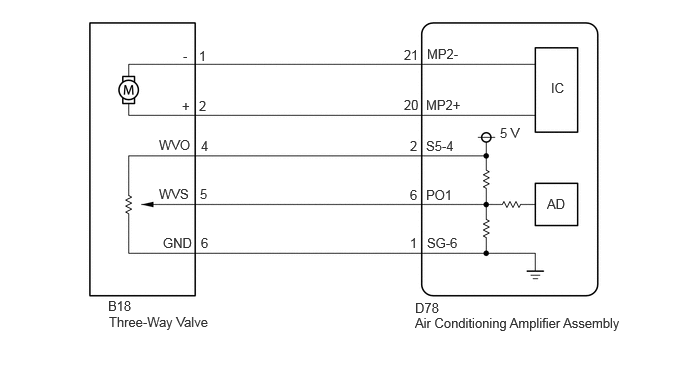
WIRING DIAGRAM
PROCEDURE
Pre-procedure1
Remove the air conditioning amplifier assembly with connectors still connected.
Check the operation by referring to the table below.
- Body Electrical > Air Conditioner > Active Test
-
Tester Display Measurement Item Control Range Diagnostic Note Heater Valve Tree-way valve Close, Half, Open -
- Body Electrical > Air Conditioner > Active Test
-
Tester Display Heater Valve - 50004 121 103
Procedure1
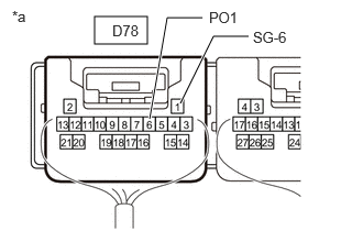
| *a | Component with harness connected
(to Air Conditioning Amplifier Assembly) |
Measure the voltage according to the value(s) in the table below.
- Standard Voltage:
Tester Connection Condition Specified Condition Click Location & Routing(D78)Location & Routingewd_type=routing;type=c;code=D78
Click Connector(D78)Instrument Panel>Instrument Panel Wire>Air Conditioning Amplifier Assemblyewd_type=component;type=c;code=D78;pinno=6,1
D78-6 (PO1) - D78-1 (SG-6) Active Test "Close" 2.3 to 2.7 V D78-6 (PO1) - D78-1 (SG-6) Active Test "Half" 1.3 to 1.7 V D78-6 (PO1) - D78-1 (SG-6) Active Test "Open" 0.3 to 0.7 V
- Result:
Proceed to OK NG
Post-procedure1
None
OK
NG
Pre-procedure1
Disconnect the B18 three-way valve connector.
Disconnect the D78 air conditioning amplifier assembly connector.
Procedure1
Measure the resistance according to the value (s) in the table below.
- Standard Resistance:
Tester Connection Condition Specified Condition Click Location & Routing(B18,D78)Location & Routingewd_type=routing;type=c,c;code=B18,D78
Click Connector(B18)Engine Compartment>No. 2 Stack Wire>Heater Accessory Assemblyewd_type=component;type=c;code=B18;pinno=1,2,4,5,6
Click Connector(D78)Instrument Panel>Instrument Panel Wire>Air Conditioning Amplifier Assemblyewd_type=component;type=c;code=D78;pinno=21,20,2,6,1
B18-1 (-) - D78-21 (MP2-) Always Below 1 Ω B18-2 (+) - D78-20 (MP2+) Always Below 1 Ω B18-4 (WVO) - D78-2 (S 5-4) Always Below 1 Ω B18-5 (WVS) - D78-6 (PO1) Always Below 1 Ω B18-6 (GND) - D78-1 (SG-6) Always Below 1 Ω B18-1 (-) or D78-21 (MP2-) - Body ground Always 10 kΩ or higher B18-2 (+) or D78-20 (MP2+) - Body ground Always 10 kΩ or higher B18-4 (WVO) or D78-2 (S 5-4) - Body ground Always 10 kΩ or higher B18-5 (WVS) or D78-6 (PO1) - Body ground Always 10 kΩ or higher B18-6 (GND) or D78-1 (SG-6) - Body ground Always 10 kΩ or higher
- Result:
Proceed to OK NG
Post-procedure1
None
OK
NG
Replace the three-way valve with a new or known good one.
- HINT:
-
Click hereVehicle Interior>HEATING / AIR CONDITIONING>MAGNET VALVE (for Three-Way Valve)>REMOVAL
- Result:
Proceed to NEXT
NEXT
Check for DTCs.
- Body Electrical > Air Conditioner > Trouble Codes
- 50001 121
- Result:
Result Proceed to B14AB is not output A B14AB is output B
A
B