HYBRID / BATTERY CONTROL HYBRID CONTROL SYSTEM TERMINALS OF ECU
EV CONTROL ECU
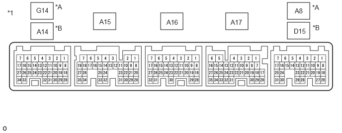
| *A | for LHD | *B | for RHD |
| *1 | EV Control ECU | - | - |
| Terminal No.
(Symbol) |
Terminal Description | Condition | Specified Condition |
|---|---|---|---|
|
*1: for LHD *2: for RHD *3: for 1500W Type Voltage Inverter |
|||
| A8-1 (BATT) - A17-4 (E1)*1
D15-1 (BATT) - A17-4 (E1)*2 |
Constant power source | Ignition switch ON | 11 to 14 V |
| Ignition switch ON (READY) | 11 to 15.5 V | ||
| A16-7 (IG2) - A17-4 (E1) | Power source | Ignition switch ON | 11 to 14 V |
| A17-1 (+B1) - A17-4 (E1) | Power source | Ignition switch ON | 11 to 14 V |
| A8-7 (+B2) - A17-4 (E1)*1
D15-7 (+B2) - A17-4 (E1)*2 |
Power source | Ignition switch ON | 11 to 14 V |
| A8-21 (MREL) - A17-4 (E1)*1
D15-21 (MREL) - A17-4 (E1)*2 |
Main relay | Ignition switch ON | 11 to 14 V |
| A17-13 (LIN3) - A17-4 (E1) | LIN communication signal
(A/C inverter, auxiliary battery state sensor) |
Ignition switch ON (READY) | Pulse generation |
| G14-3 (RLAC) - A17-4 (E1)*1
A14-3 (RLAC) - A17-4 (E1)*2 |
A/C relay | Ignition switch ON | 11 to 14 V |
| A17-6 (VCPA) - A17-27 (EPA) | Accelerator pedal (with sensor) rod assembly power source (for VPA) | Ignition switch ON | 4.5 to 5.5 V |
| A17-33 (VPA2) - A17-25 (EPA2) | Accelerator pedal (with sensor) rod assembly (for accelerator pedal sensor malfunction detection) | Ignition switch ON, accelerator pedal released | 1.0 to 2.2 V |
| Ignition switch ON, Hybrid control stem stopped, shift state in park (P), accelerator pedal fully depressed | 3.4 to 5.3 V | ||
| A17-35 (VPA) - A17-27 (EPA) | Accelerator pedal (with sensor) rod assembly (for accelerator pedal position detection) | Ignition switch ON, accelerator pedal released | 0.4 to 1.4 V |
| Ignition switch ON, Hybrid control stem stopped, shift state in park (P), accelerator pedal fully depressed | 2.6 to 4.5 V | ||
| A17-5 (VCP2) - A17-25 (EPA2) | Accelerator pedal (with sensor) rod assembly power source (for VPA2) | Ignition switch ON | 4.5 to 5.5 V |
| G14-9 (OPM2) - A17-4 (E1)*1
A14-9 (OPM2) - A17-4 (E1)*2 |
OIL PMP MTR relay | Ignition switch ON (READY) | 11 to 14 V |
| G14-15 (OPM1) - A17-4 (E1)*1
A14-15 (OPM1) - A17-4 (E1)*2 |
Oil with motor pump assembly signal | Ignition switch ON (READY) | Pulse generation
(Waveform 1) |
| G14-10 (NOPM) - A17-4 (E1)*1
A14-10 (NOPM) - A17-4 (E1)*2 |
Oil with motor pump assembly signal | Ignition switch ON (READY) | Pulse generation
(Waveform 1) |
| A17-7 (STP) - A17-4 (E1) | Stop light switch | Brake pedal depressed | 11 to 14 V |
| Brake pedal released | 0 to 1.5 V | ||
| A16-1 (ST1-) - A17-4 (E1) | Stop light switch signal | Brake pedal depressed | 0 to 1.5 V |
| Brake pedal released | 11 to 14 V | ||
| A17-30 (IWP) - A17-4 (E1) | Water with motor pump assembly signal | Ignition switch ON (READY) | Pulse generation
(Waveform 2) |
| A17-10 (NIWP) - A17-4 (E1) | Water with motor pump assembly signal | Ignition switch ON (READY) | Pulse generation
(Waveform 2) |
| A17-9 (IDH) - A17-4 (E1) | External load operation prohibition request signal | Ignition switch ON | 0 to 2 V |
| A17-18 (NODD) - A17-4 (E1) | DC/DC operation | DC/DC converter operating normally | 5 to 7 V |
| DC/DC converter not operating normally | 2 to 4 V | ||
| DC/DC converter operating prohibited | 0.1 to 0.5 V | ||
| A17-17 (VLO) - A17-4 (E1) | DC/DC operation monitor / voltage change signal | Ignition switch ON | Pulse generation
(Waveform 3) |
| G14-21 (MMT) - G14-31 (MMTG)*1
A14-21 (MMT) - A14-31 (MMTG)*2 |
Motor temperature sensor | Ignition switch ON, temperature 25°C (77°F) | 3.6 to 4.6 V |
| Ignition switch ON, temperature 60°C (140°F) | 2.2 to 3.2 V | ||
| A15-20 (TTA) - A15-28 (ETTA) | Transaxle fluid temperature sensor | Ignition switch ON, temperature 25°C (77°F) | 3.6 to 4.6 V |
| Ignition switch ON, temperature 60°C (140°F) | 2.2 to 3.2 V | ||
| A17-8 (HSDN) - A17-4 (E1) | MG ECU shutdown signal | Ignition switch ON (READY) | 0 to 1.5 V |
| A16-17 (MTH-) - A17-4 (E1) | Communication signal from MG ECU to EV control ECU | Ignition switch ON (READY) | Pulse generation
(Waveform 4) |
| A16-16 (MTH+) - A17-4 (E1) | Communication signal from MG ECU to EV control ECU | Ignition switch ON (READY) | Pulse generation
(Waveform 4) |
| A16-10 (HTM+) - A17-4 (E1) | Communication signal from EV control ECU to MG ECU | Ignition switch ON (READY) | Pulse generation
(Waveform 5) |
| A16-11 (HTM-) - A17-4 (E1) | Communication signal from EV control ECU to MG ECU | Ignition switch ON (READY) | Pulse generation
(Waveform 5) |
| A16-15 (REQ-) - A17-4 (E1) | MG ECU communication request signal | Ignition switch ON (READY) | Pulse generation
(Waveform 6) |
| A16-14 (REQ+) - A17-4 (E1) | MG ECU communication request signal | Ignition switch ON (READY) | Pulse generation
(Waveform 6) |
| A16-13 (CLK-) - A17-4 (E1) | MG communication clock signal | Ignition switch ON | Pulse generation
(Waveform 7) |
| A16-12 (CLK+) - A17-4 (E1) | MG communication clock signal | Ignition switch ON | Pulse generation
(Waveform 7) |
| G14-2 (SMRG) - A17-3 (E01)*1
A14-2 (SMRG) - A17-3 (E01)*2 |
System main relay operation signal | Ignition switch ON→Ignition switch ON (READY) | Pulse generation
(Waveform 8) |
| G14-14 (SMRP) - A17-3 (E01)*1
A14-14 (SMRP) - A17-3 (E01)*2 |
System main relay operation signal | Ignition switch ON→Ignition switch ON (READY) | Pulse generation
(Waveform 8) |
| G14-4 (SMRB) - A17-3 (E01)*1
A14-4 (SMRB) - A17-3 (E01)*2 |
System main relay operation signal | Ignition switch ON→Ignition switch ON (READY) | Pulse generation
(Waveform 8) |
| A8-19 (ST2) - A17-4 (E1)*1
D15-19 (ST2) - A17-4 (E1)*2 |
Starter signal | Ignition switch ON | 0 to 1.5 V |
| A8-18 (IGB) - A17-4 (E1)*1
D15-18 (IGB) - A17-4 (E1)*2 |
Power source | Ignition switch ON | 11 to 14 V |
| A8-27 (ACIM) - A17-4 (E1) | Voltage inverter operation monitor signal*3 | Ignition switch ON (READY), power outlet switch ON (voltage inverter outputting) | 0 to 1.5 V |
| Ignition switch ON (READY), power outlet switch OFF (voltage inverter stopped) | 4.5 to 5.5 V | ||
| A8-12 (NOAC) - A17-4 (E1) | Voltage inverter prohibition request signal*3 | Ignition switch ON (READY), Voltage inverter operation permission signal being received | 5.9 to 10.9 V |
| Ignition switch ON (READY), Voltage inverter operation prohibition signal being received | 0.1 to 0.5 V | ||
| A17-11 (VAIN) - A17-4 (E1) | Voltage inverter output voltage signal*3 | READY ON, Voltage inverter stopped | 2.828 to 4.500 V |
| READY ON, Voltage inverter outputting | 0.500 to 2.827 V | ||
| G14-11 (ACSW) - A17-4 (E1) | Voltage inverter operation signal*3 | Ignition switch ON (READY), accessory power outlet system operating | 11 to 14 V |
| Ignition switch ON (READY), accessory power outlet system not operating | 0 to 1.5 V | ||
| A8-23 (HCIV) - A17-4 (E1) | Power outlet switch signal*3 | Ignition switch ON, Power outlet switch not operated | 11 to 14 V |
| Ignition switch ON, Power outlet switch being pushed and held | 0 to 1.5 V | ||
| A17-29 (ACIN) - A17-4 (E1) | Power outlet switch signal*3 | Ignition switch ON (READY), accessory power outlet system operating | 11 to 14 V |
| Ignition switch ON (READY), accessory power outlet system not operating | 0 to 1.5 V | ||
| A8-10 (SBFS) - A17-4 (E1)*1
D15-10 (SBFS) - A17-4 (E1)*2 |
Electronic shift lever system fail safe signal | Ignition switch ON | Pulse generation
(Waveform 9) |
| A8-25 (DMS+) - A17-4 (E1)*1
D15-25 (DMS+) - A17-4 (E1)*2 |
DRIVE MODE switch (NO. 1 Pattern Select Switch Assembly) signal | Ignition switch ON, DRIVE MODE switch (NO. 1 Pattern Select Switch Assembly) not pushed | 11 to 14 V |
| Ignition switch ON, DRIVE MODE switch (NO. 1 Pattern Select Switch Assembly) pushed and held | 0 to 1.5 V | ||
| A8-30 (DMS-) - A17-4 (E1)*1
D15-30 (DMS-) - A17-4 (E1)*2 |
DRIVE MODE switch (NO. 1 Pattern Select Switch Assembly) signal | Ignition switch ON, DRIVE MODE switch (NO. 1 Pattern Select Switch Assembly) not pushed | 11 to 14 V |
| Ignition switch ON, DRIVE MODE switch (NO. 1 Pattern Select Switch Assembly) pushed and held | 0 to 1.5 V | ||
| A8-24 (SNOW) - A17-4 (E1)*1
D15-24 (SNOW) - A17-4 (E1)*2 |
SNOW mode switch (Pattern Select Switch Assembly) signal | Ignition switch ON, SNOW mode switch (Pattern Select Switch Assembly) not turned | 11 to 14 V |
| Ignition switch ON, SNOW mode switch (Pattern Select Switch Assembly) being turned and held | 0 to 1.5 V | ||
| A17-28 (ILK) - A17-4 (E1) | Interlock switch | Ignition switch ON, connector cover assembly, inverter terminal cover, front compartment main wire and service plug grip installed correctly | 0 to 1.5 V |
| Ignition switch ON, connector cover assembly, inverter terminal cover, front compartment main wire and service plug grip not installed | 11 to 14 V | ||
| A17-2 (FSDN) - A17-4 (E1) | FC emergency shutdown signal | Ignition switch ON (READY) | 0 to 1.5 V |
| A16-20 (ISDN) - A17-4 (E1) | Boosting converter (EV) fail signal | Ignition switch ON (READY) | 0 to 1.5 V |
| A15-7 (SILK) - A17-4 (E1) | FC interlock switch | FC converter power outlet cable installed | 0 to 1.5 V |
| A16-6 (FRP) - A17-4 (E1) | FC precharge junction assembly (FRP) operation signal | Ignition switch ON→Ignition switch ON (READY) | Pulse generation
(Waveform 10) |
| A16-3 (FRB+) - A16-5 (FRB-) | FC stack main relay (FRB) operation signal | Ignition switch ON→Ignition switch ON (READY) | Pulse generation
(Waveform 10) |
| A15-3 (FRG+) - A15-2 (FRG-) | FC stack main relay (FRG) operation signal | Ignition switch ON→Ignition switch ON (READY) | Pulse generation
(Waveform 10) |
| A8-22 (ABFS) - A17-4 (E1)*1
D15-22 (ABFS) - A17-4 (E1)*2 |
Airbag activation signal | Ignition switch ON (READY) | Pulse generation
(Waveform 11) |
| A8-17 (CA1L) - A17-4 (E1)*1
D15-17 (CA1L) - A17-4 (E1)*2 |
CAN communication signal | Ignition switch ON | Pulse generation
(Waveform 12) |
| A8-16 (CA1H) - A17-4 (E1)*1
D15-16 (CA1H) - A17-4 (E1)*2 |
CAN communication signal | Ignition switch ON | Pulse generation
(Waveform 12) |
| A8-15 (CA3N) - A17-4 (E1)*1
D15-15 (CA3N) - A17-4 (E1)*2 |
CAN communication signal | Ignition switch ON | Pulse generation
(Waveform 13) |
| A8-14 (CA3P) - A17-4 (E1)*1
D15-14 (CA3P) - A17-4 (E1)*2 |
CAN communication signal | Ignition switch ON | Pulse generation
(Waveform 13) |
| A8-2 (CA4H) - A17-4 (E1)*1
D15-2 (CA4H) - A17-4 (E1)*2 |
CAN communication signal | Ignition switch ON | Pulse generation
(Waveform 14) |
| A8-3 (CA4L) - A17-4 (E1)*1
D15-3 (CA4L) - A17-4 (E1)*2 |
CAN communication signal | Ignition switch ON | Pulse generation
(Waveform 14) |
| A16-22 (DRN3) - Body ground | Shield ground | Always | Below 1 Ω |
| A17-4 (E1) - Body ground | Ground | Always | Below 1 Ω |
| A15-35 (EC1) - Body ground | Ground | Always | Below 1 Ω |
| A17-32 (EC2) - Body ground | Ground | Always | Below 1 Ω |
| A17-3 (E01) - Body ground | Ground | Always | Below 1 Ω |
| A8-5 (E02) - Body ground*1
D15-5 (E02) - Body ground*2 |
Ground | Always | Below 1 Ω |
| A8-4 (E12) - Body ground*1
D15-4 (E12) - Body ground*2 |
Ground | Always | Below 1 Ω |
Oscilloscope waveforms
- HINT:
-
Oscilloscope waveform samples are provided here for informational purposes. Noise and fluttering waveforms have been omitted.
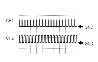
Waveform 1 (Oil with pump motor signal)
| Item | Content |
|---|---|
| Terminal | CH1: G14-15 (OPM1) - A17-4 (E1)
CH2: G14-10 (NOPM) - A17-4 (E1) |
| Equipment Setting | 10 V/DIV., 20 ms/DIV |
| Condition | Ignition switch ON (READY) |
| Item | Content |
|---|---|
| Terminal | CH1: A14-15 (OPM1) - A17-4 (E1)
CH2: A14-10 (NOPM) - A17-4 (E1) |
| Equipment Setting | 10 V/DIV., 20 ms/DIV |
| Condition | Ignition switch ON (READY) |
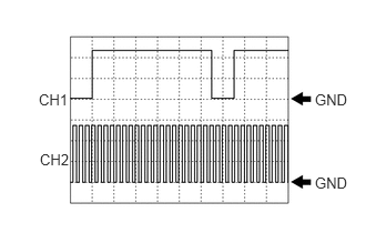
Waveform 2 (Water with motor pump signal)
| Item | Content |
|---|---|
| Terminal | CH1: A17-30 (IWP) - A17-4 (E1)
CH2: A17-10 (NIWP) - A17-4 (E1) |
| Equipment Setting | 5 V/DIV., 20 ms./DIV. |
| Condition | Ignition switch ON (READY) |
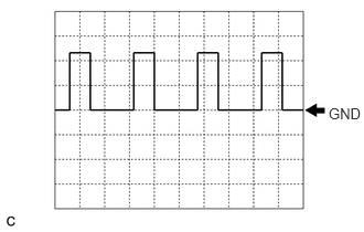
Waveform 3 (DC/DC operation monitor/voltage change signal)
| Item | Content |
|---|---|
| Terminal | A17-17 (VLO) - A17-4 (E1) |
| Equipment Setting | 5 V/DIV., 50 ms./DIV. |
| Condition | Ignition switch ON |
- HINT:
-
The cycle will vary depending on the specified voltage of the DC/DC converter.
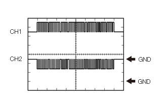
Waveform 4 (Communication signal from MG ECU to EV control ECU)
| Item | Content |
|---|---|
| Terminal | CH1: A16-16 (MTH+) - A17-4 (E1)
CH2: A16-17 (MTH-) - A17-4 (E1) |
| Equipment Setting | 1 V/DIV., 200 μs./DIV. |
| Condition | Ignition switch ON (READY) |
- HINT:
-
The waveform will vary depending on the content of the digital communication (digital signal).
Waveform 6 (Communication signal from EV control ECU to MG ECU)
| Item | Content |
|---|---|
| Terminal | CH1: A16-10 (HTM+) - A17-4 (E1)
CH2: A16-11 (HTM-) - A17-4 (E1) |
| Equipment Setting | 1 V/DIV., 200 μs./DIV. |
| Condition | Ignition switch ON (READY) |
- HINT:
-
The waveform will vary depending on the content of the digital communication (digital signal).
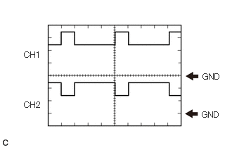
Waveform 6 (MG ECU communication request signal)
| Item | Content |
|---|---|
| Terminal | CH1: A16-14 (REQ+) - A17-4 (E1)
CH2: A16-15 (REQ-) - A17-4 (E1) |
| Equipment Setting | 1 V/DIV., 1 ms./DIV. |
| Condition | Ignition switch ON (READY) |
Waveform 7 (MG communication clock signal)
| Item | Content |
|---|---|
| Terminal | CH1: A16-12 (CLK+) - A17-4 (E1)
CH2: A16-13 (CLK-) - A17-4 (E1) |
| Equipment Setting | 1 V/DIV., 1 μs./DIV. |
| Condition | Ignition switch ON (READY) |
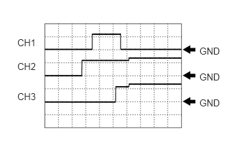
Waveform 8 (System main relay operation signal)
| Item | Content |
|---|---|
| Terminal | CH1: G14-14 (SMRP) - A17-3 (E01)
CH2: G14-4 (SMRB) - A17-3 (E01) CH3: G14-2 (SMRG) - A17-3 (E01) |
| Equipment Setting | 10 V/DIV., 200 ms./DIV. |
| Condition | Ignition switch ON→Ignition switch ON (READY) |
| Item | Content |
|---|---|
| Terminal | CH1: A14-14 (SMRP) - A17-3 (E01)
CH2: A14-4 (SMRB) - A17-3 (E01) CH3: A14-2 (SMRG) - A17-3 (E01) |
| Equipment Setting | 10 V/DIV., 200 ms./DIV. |
| Condition | Ignition switch ON→Ignition switch ON (READY) |
- HINT:
-
The waveform will vary depending on the content of the digital communication (digital signal).
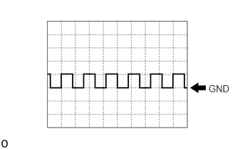
Waveform 9 (Electronic shift lever system fail-safe signal)
| Item | Content |
|---|---|
| Terminal | A8-10 (SBFS) - A17-4 (E1) |
| Equipment Setting | 10 V/DIV., 20 ms./DIV. |
| Condition | Ignition switch ON |
| Item | Content |
|---|---|
| Terminal | D15-10 (SBFS) - A17-4 (E1) |
| Equipment Setting | 10 V/DIV., 20 ms./DIV. |
| Condition | Ignition switch ON |
- HINT:
-
The waveform will vary depending on the content of the digital communication (digital signal).
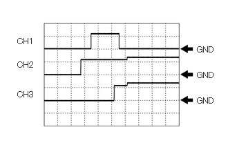
Waveform 10 (FC stack main relay, FC precharge junction assembly operation signal)
| Item | Content |
|---|---|
| Terminal | CH1: A16-6 (FRP) - A17-4 (E1)
CH2: A16-3 (FRB+) - A16-5 (FRB-) CH3: A15-3 (FRG+) - A15-2 (FRG-) |
| Equipment Setting | 10 V/DIV., 200 ms/DIV. |
| Condition | Ignition switch ON→Ignition switch ON (READY) |
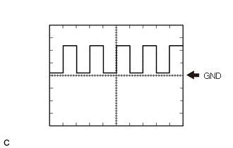
Waveform 11 (Airbag activation signal)
| Item | Content |
|---|---|
| Terminal | A8-22 (ABFS) - A17-4 (E1) |
| Equipment Setting | 5 V/DIV., 150 ms./DIV. |
| Condition | READY ON |
| Item | Content |
|---|---|
| Terminal | D15-22 (ABFS) - A17-4 (E1) |
| Equipment Setting | 5 V/DIV., 150 ms./DIV. |
| Condition | READY ON |
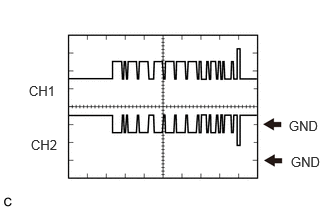
Waveform 12 (CAN communication signal)
| Item | Content |
|---|---|
| Terminal | CH1: A8-16 (CA1H) - A17-4 (E1)
CH2: A8-17 (CA1L) - A17-4 (E1) |
| Equipment Setting | 1 V/DIV., 50 μs./DIV. |
| Condition | Ignition switch ON |
| Item | Content |
|---|---|
| Terminal | CH1: D15-16 (CA1H) - A17-4 (E1)
CH2: D15-17 (CA1L) - A17-4 (E1) |
| Equipment Setting | 1 V/DIV., 50 μs./DIV. |
| Condition | Ignition switch ON |
- HINT:
-
The waveform will vary depending on the content of the digital communication (digital signal).
Waveform 13 (CAN communication signal)
| Item | Content |
|---|---|
| Terminal | CH1: A8-14 (CA3P) - A17-4 (E1)
CH2: A8-15 (CA3N) - A17-4 (E1) |
| Equipment Setting | 1 V/DIV., 50 μs./DIV. |
| Condition | Ignition switch ON |
| Item | Content |
|---|---|
| Terminal | CH1: D15-14 (CA3P) - A17-4 (E1)
CH2: D15-15 (CA3N) - A17-4 (E1) |
| Equipment Setting | 1 V/DIV., 50 μs./DIV. |
| Condition | Ignition switch ON |
- HINT:
-
The waveform will vary depending on the content of the digital communication (digital signal).
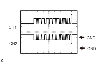
Waveform 14 (CAN communication signal)
| Item | Content |
|---|---|
| Terminal | CH1: A8-2 (CA4H) - A17-4 (E1)
CH2: A8-3 (CA4L) - A17-4 (E1) |
| Equipment Setting | 1 V/DIV., 50 μs./DIV. |
| Condition | Ignition switch ON |
| Item | Content |
|---|---|
| Terminal | CH1: D15-2 (CA4H) - A17-4 (E1)
CH2: D15-3 (CA4L) - A17-4 (E1) |
| Equipment Setting | 1 V/DIV., 50 μs./DIV. |
| Condition | Ignition switch ON |
- HINT:
-
The waveform will vary depending on the content of the digital communication (digital signal).
Inverter with Converter Assembly
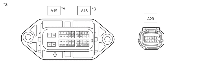
| *A | for LHD | *B | for RHD |
| *a | Inverter with Converter Assembly | - | - |
- HINT:
-
Since the inverter with converter assembly uses waterproof connectors, the voltage and waveforms cannot be inspected directly. Standard voltage readings and waveforms are indicated for reference only.
| Terminal No.
(Symbol) |
Terminal Description | Condition | Standard Condition |
|---|---|---|---|
| A19-2 (MTH-) - A19-30 (GND1) | Communication signal from MG ECU to EV control ECU | Ignition switch ON (READY) | Pulse generation
(Waveform 2) |
| A19-3 (MTH+) - A19-30 (GND1) | Communication signal from EV control ECU to MG ECU | Ignition switch ON (READY) | Pulse generation
(Waveform 2) |
| A19-10 (+B) - A19-30 (GND1) | MG ECU power source | Ignition switch ON | 11 to 14 V |
| A19-11 (+B2) - A19-30 (GND1) | MG ECU power source | Ignition switch ON | 11 to 14 V |
| A19-13 (CLK-) - A19-30 (GND1) | MG ECU communication clock signal | Ignition switch ON (READY) | Pulse generation
(Waveform 1) |
| A19-14 (CLK+) - A19-30 (GND1) | MG ECU communication clock signal | Ignition switch ON (READY) | Pulse generation
(Waveform 1) |
| A19-17 (GCS) - A19-6 (GCSG) | FC air compressor motor resolver signal | FC air compressor motor resolver running | Pulse generation
(Waveform 5) |
| A19-18 (GSN) - A19-7 (GSNG) | FC air compressor motor resolver signal | FC air compressor motor resolver running | Pulse generation
(Waveform 5) |
| A19-20 (GRF) - A19-9 (GRFG) | FC air compressor motor resolver signal | FC air compressor motor resolver running | Pulse generation
(Waveform 5) |
| A19-22 (HTM-) - A19-30 (GND1) | Communication signal from EV control ECU to MG ECU | Ignition switch ON (READY) | Pulse generation
(Waveform 3) |
| A19-23 (HTM+) - A19-30 (GND1) | Communication signal from EV control ECU to MG ECU | Ignition switch ON (READY) | Pulse generation
(Waveform 3) |
| A19-24 (ILKO) - A19-30 (GND1) | Interlock switch signal | Ignition switch ON, connector cover assembly, inverter terminal cover, front compartment main wire and service plug grip installed correctly | Below 1 V |
| Ignition switch ON, connector cover assembly, inverter terminal cover, front compartment main wire and service plug grip not installed | 11 to 14 V | ||
| A19-25 (HSDN) - A19-30 (GND1) | MG shutdown signal | Ignition switch ON (READY) | 0 to 1 V |
| A19-33 (REQ-) - A19-30 (GND1) | MG ECU communication request signal | Ignition switch ON (READY) | Pulse generation
(Waveform 4) |
| A19-34 (REQ+) - A19-30 (GND1) | MG ECU communication request signal | Ignition switch ON (READY) | Pulse generation
(Waveform 4) |
| A19-35 (ILKI) - A19-30 (GND1) | Interlock switch signal | Ignition switch ON, connector cover assembly, inverter terminal cover, front compartment main wire and service plug grip installed correctly | Below 1 V |
| Ignition switch ON, connector cover assembly, inverter terminal cover, front compartment main wire and service plug grip not installed | 11 to 14 V | ||
| A19-38 (MCS) - A19-27 (MCSG) | Drive motor resolver signal | Drive motor resolver running | Pulse generation
(Waveform 6) |
| A19-39 (MSN) - A19-28 (MSNG) | Drive motor resolver signal | Drive motor resolver running | Pulse generation
(Waveform 6) |
| A19-40 (MRF) - A19-29 (MRFG) | Drive motor resolver signal | Drive motor resolver running | Pulse generation
(Waveform 6) |
| A20-1 (IGCT) - A19-30 (GND1) | MG ECU power source | Ignition switch ON | 11 to 14 V |
| A20-2 (IDH) - A19-30 (GND1) | Heater prohibit signal | Ignition switch ON | 4 to 6 V |
| A20-3 (S) - A19-30 (GND1) | Auxiliary battery voltage monitor | Ignition switch ON | 11 to 14 V |
| A20-5 (NODD) - A19-30 (GND1) | DC/DC operation | DC/DC converter operating normally | 5 to 7 V |
| DC/DC converter not operating normally | 2 to 4 V | ||
| DC/DC converter operation prohibited | 0.1 to 0.5 V | ||
| A20-6 (VLO) - A19-30 (GND1) | DC/DC operation monitor / voltage change signal | Ignition switch ON | Pulse generation
(Waveform 7) |
| Terminal No.
(Symbol) |
Terminal Description | Condition | Standard Condition |
|---|---|---|---|
| A18-2 (MTH-) - A18-30 (GND1) | Communication signal from MG ECU to EV control ECU | Ignition switch ON (READY) | Pulse generation
(Waveform 2) |
| A18-3 (MTH+) - A18-30 (GND1) | Communication signal from EV control ECU to MG ECU | Ignition switch ON (READY) | Pulse generation
(Waveform 2) |
| A18-10 (+B) - A18-30 (GND1) | MG ECU power source | Ignition switch ON | 11 to 14 V |
| A18-11 (+B2) - A18-30 (GND1) | MG ECU power source | Ignition switch ON | 11 to 14 V |
| A18-13 (CLK-) - A18-30 (GND1) | MG ECU communication clock signal | Ignition switch ON (READY) | Pulse generation
(Waveform 1) |
| A18-14 (CLK+) - A18-30 (GND1) | MG ECU communication clock signal | Ignition switch ON (READY) | Pulse generation
(Waveform 1) |
| A18-17 (GCS) - A18-6 (GCSG) | FC air compressor motor resolver signal | FC air compressor motor resolver running | Pulse generation
(Waveform 5) |
| A18-18 (GSN) - A18-7 (GSNG) | FC air compressor motor resolver signal | FC air compressor motor resolver running | Pulse generation
(Waveform 5) |
| A18-20 (GRF) - A18-9 (GRFG) | FC air compressor motor resolver signal | FC air compressor motor resolver running | Pulse generation
(Waveform 5) |
| A18-22 (HTM-) - A18-30 (GND1) | Communication signal from EV control ECU to MG ECU | Ignition switch ON (READY) | Pulse generation
(Waveform 3) |
| A18-23 (HTM+) - A18-30 (GND1) | Communication signal from EV control ECU to MG ECU | Ignition switch ON (READY) | Pulse generation
(Waveform 3) |
| A18-24 (ILKO) - A18-30 (GND1) | Interlock switch signal | Ignition switch ON, connector cover assembly, inverter terminal cover, front compartment main wire and service plug grip installed correctly | Below 1 V |
| Ignition switch ON, connector cover assembly, inverter terminal cover, front compartment main wire and service plug grip not installed | 11 to 14 V | ||
| A18-25 (HSDN) - A18-30 (GND1) | MG shutdown signal | Ignition switch ON (READY) | 0 to 1 V |
| A18-33 (REQ-) - A18-30 (GND1) | MG ECU communication request signal | Ignition switch ON (READY) | Pulse generation
(Waveform 4) |
| A18-34 (REQ+) - A18-30 (GND1) | MG ECU communication request signal | Ignition switch ON (READY) | Pulse generation
(Waveform 4) |
| A18-35 (ILKI) - A18-30 (GND1) | Interlock switch signal | Ignition switch ON, connector cover assembly, inverter terminal cover, front compartment main wire and service plug grip installed correctly | Below 1 V |
| Ignition switch ON, connector cover assembly, inverter terminal cover, front compartment main wire and service plug grip not installed | 11 to 14 V | ||
| A18-38 (MCS) - A18-27 (MCSG) | Drive motor resolver signal | Drive motor resolver running | Pulse generation
(Waveform 6) |
| A18-39 (MSN) - A18-28 (MSNG) | Drive motor resolver signal | Drive motor resolver running | Pulse generation
(Waveform 6) |
| A18-40 (MRF) - A18-29 (MRFG) | Drive motor resolver signal | Drive motor resolver running | Pulse generation
(Waveform 6) |
| A20-1 (IGCT) - A18-30 (GND1) | MG ECU power source | Ignition switch ON | 11 to 14 V |
| A20-2 (IDH) - A18-30 (GND1) | Heater prohibit signal | Ignition switch ON | 4 to 6 V |
| A20-3 (S) - A18-30 (GND1) | Auxiliary battery voltage monitor | Ignition switch ON | 11 to 14 V |
| A20-5 (NODD) - A18-30 (GND1) | DC/DC operation | DC/DC converter operating normally | 5 to 7 V |
| DC/DC converter not operating normally | 2 to 4 V | ||
| DC/DC converter operation prohibited | 0.1 to 0.5 V | ||
| A20-6 (VLO) - A18-30 (GND1) | DC/DC operation monitor / voltage change signal | Ignition switch ON | Pulse generation
(Waveform 7) |
- NOTICE:
-
Do not measure the voltage or waveform on the sealed side of the inverter with converter assembly connector. Doing so may damage the connector because the connector is waterproof.
Oscilloscope waveforms
- HINT:
-
Oscilloscope waveforms shown in the illustrations are examples for reference only. Noise, chattering, etc. are not shown.
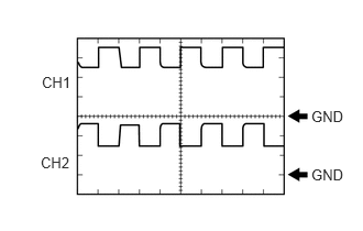
Waveform 1 (MG ECU communication clock signal)
| Item | Content |
|---|---|
| Terminal | CH1: A19-13 (CLK-) - A19-30 (GND1)
CH2: A19-14 (CLK+) - A19-30 (GND1) |
| Equipment Setting | 1 V/DIV., 1 μs./DIV. |
| Condition | Ignition switch ON (READY) |
| Item | Content |
|---|---|
| Terminal | CH1: A18-13 (CLK-) - A18-30 (GND1)
CH2: A18-14 (CLK+) - A18-30 (GND1) |
| Equipment Setting | 1 V/DIV., 1 μs./DIV. |
| Condition | Ignition switch ON (READY) |
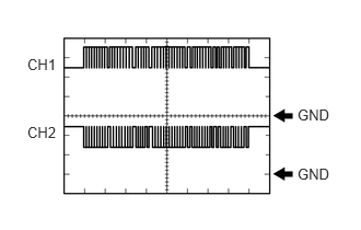
Waveform 2 (Communication signal from MG ECU to EV control ECU)
| Item | Content |
|---|---|
| Terminal | CH1: A19-2 (MTH-) - A19-30 (GND1)
CH2: A19-3 (MTH+) - A19-30 (GND1) |
| Equipment Setting | 1 V/DIV., 200 μs./DIV. |
| Condition | Ignition switch ON (READY) |
| Item | Content |
|---|---|
| Terminal | CH1: A18-2 (MTH-) - A18-30 (GND1)
CH2: A18-3 (MTH+) - A18-30 (GND1) |
| Equipment Setting | 1 V/DIV., 200 μs./DIV. |
| Condition | Ignition switch ON (READY) |
- HINT:
-
The waveform will vary depending on the content of the digital communication (digital signal).
Waveform 3 (Communication signal from EV control ECU to MG ECU)
| Item | Content |
|---|---|
| Terminal | CH1: A19-22 (HTM-) - A19-30 (GND1)
CH2: A19-23 (HTM+) - A19-30 (GND1) |
| Equipment Setting | 1 V/DIV., 200 μs./DIV. |
| Condition | Ignition switch ON (READY) |
| Item | Content |
|---|---|
| Terminal | CH1: A18-22 (HTM-) - A18-30 (GND1)
CH2: A18-23 (HTM+) - A18-30 (GND1) |
| Equipment Setting | 1 V/DIV., 200 μs./DIV. |
| Condition | Ignition switch ON (READY) |
- HINT:
-
The waveform will vary depending on the content of the digital communication (digital signal).
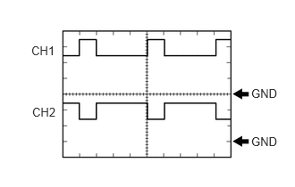
Waveform 4 (MG ECU communication request signal)
| Item | Content |
|---|---|
| Terminal | CH1: A19-33 (REQ-) - A19-30 (GND1)
CH2: A19-34 (REQ+) - A19-30 (GND1) |
| Equipment Setting | 1 V/DIV., 1 ms./DIV. |
| Condition | Ignition switch ON (READY) |
| Item | Content |
|---|---|
| Terminal | CH1: A18-33 (REQ-) - A18-30 (GND1)
CH2: A18-34 (REQ+) - A18-30 (GND1) |
| Equipment Setting | 1 V/DIV., 1 ms./DIV. |
| Condition | Ignition switch ON (READY) |
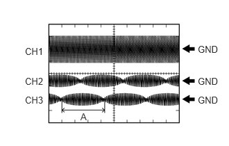
Waveform 5 (FC air compressor motor resolver signal)
| Item | Content |
|---|---|
| Terminal | CH1: A19-20 (GRF) - A19-9 (GRFG)
CH2: A19-18 (GSN) - A19-7 (GSNG) CH3: A19-17 (GCS) - A19-6 (GCSG) |
| Equipment Setting | CH1: 10 V/DIV., 1 ms./DIV.
CH2, 3: 5 V/DIV., 1 ms./DIV. |
| Condition | FC Air Compressor Motor resolver running |
| Item | Content |
|---|---|
| Terminal | CH1: A18-20 (GRF) - A18-9 (GRFG)
CH2: A18-18 (GSN) - A18-7 (GSNG) CH3: A18-17 (GCS) - A18-6 (GCSG) |
| Equipment Setting | CH1: 10 V/DIV., 1 ms./DIV.
CH2, 3: 5 V/DIV., 1 ms./DIV. |
| Condition | FC Air Compressor Motor resolver running |
- HINT:
-
Pulse cycle A becomes shorter as the rotor speed increases.
Waveform 6 (Drive motor resolver signal)
| Item | Content |
|---|---|
| Terminal | CH1: A19-40 (MRF) - A19-29 (MRFG)
CH2: A19-39 (MSN) - A19-28 (MSNG) CH3: A19-38 (MCS) - A19-27 (MCSG) |
| Equipment Setting | CH1: 10 V/DIV., 1 ms./DIV.
CH2, 3: 5 V/DIV., 1 ms./DIV. |
| Condition | Motor resolver running |
| Item | Content |
|---|---|
| Terminal | CH1: A18-40 (MRF) - A18-29 (MRFG)
CH2: A18-39 (MSN) - A18-28 (MSNG) CH3: A18-38 (MCS) - A18-27 (MCSG) |
| Equipment Setting | CH1: 10 V/DIV., 1 ms./DIV.
CH2, 3: 5 V/DIV., 1 ms./DIV. |
| Condition | Motor resolver running |
- HINT:
-
Pulse cycle A becomes shorter as the rotor speed increases.
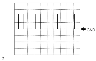
Waveform 7 (DC/DC operation monitor/voltage change signal)
| Item | Content |
|---|---|
| Terminal | A20-6 (VLO) - A19-30 (GND1) |
| Equipment Setting | 5 V/DIV., 50 ms./DIV. |
| Condition | Ignition switch ON |
- HINT:
-
The cycle will vary depending on the specified voltage of the DC/DC converter.