Vehicle position tracking methods
It is essential that the navigation system correctly tracks the current vehicle position and displays it on the map. There are 2 methods to track the current vehicle position: autonomous (dead reckoning) and GPS* (satellite) navigation. Both navigation methods are used in conjunction with each other.
- HINT:
- *: GPS (Global Positioning System)
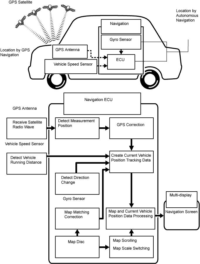
Operation Description Vehicle Position Calculation Navigation ECU calculates current vehicle position (direction and current position) using direction deviation signal from gyro sensor and running distance signal from vehicle speed sensor, and creates driving route. Map Display Processing Navigation ECU processing vehicle position data, vehicle running track, and map data from map disc. Map Matching Map data from the map disc is compared to vehicle position and running track data. Then, vehicle position is matched with nearest road. GPS Correction Vehicle position is matched to position measured by GPS. Then, measurement position data from GPS unit is compared with vehicle position and running track data. If the position is very different, GPS measurement position is used. Distance Correction Running distance signal from vehicle speed sensor includes error caused by tire wear and slippage between tires and road surface. Distance correction is performed to account for this. Navigation ECU automatically offsets the running distance signal to make up for difference between it and distance data of map. Offset is automatically updated. - HINT:
- The combination of autonomous and GPS navigation makes it possible to display the vehicle position even when the vehicle is in places where the GPS radio wave cannot receive a signal. When only autonomous navigation is used, however, the mapping accuracy may slightly decline.
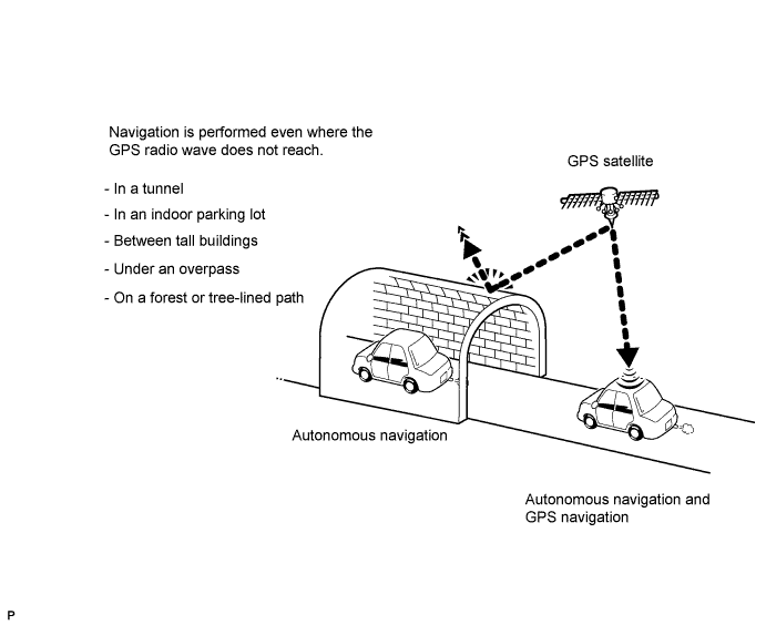
Autonomous navigation
This method determines the relative vehicle position based on the running track determined by the gyro and vehicle speed sensors located in the navigation ECU.
Gyro sensor
Calculates the direction by detecting angular velocity. It is located in the navigation ECU.Vehicle speed sensor
Used to calculated the vehicle running distance.
GPS navigation (Satellite navigation)
This method detects the absolute vehicle position using radio waves from a GPS satellite*.
- HINT:
- *: GPS satellites were launched by the U.S. Department of Defense for military purposes.
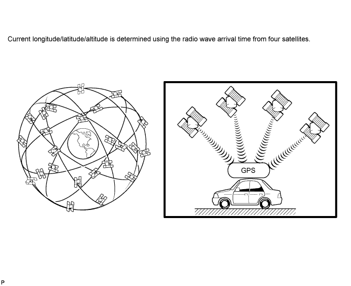
| Number of satellites | Measurement | Description |
| 2 or less | Measurement impossible | Vehicle position cannot be obtained because number of satellites is not enough. |
| 3 | 2-dimensional measurement is possible | Vehicle position is obtained based on current longitude and latitude (this is less precise than 3-dimensional measurement). |
| 4 | 3-dimensional measurement is possible | Vehicle position is obtained based on current longitude, latitude and altitude. |
Map matching
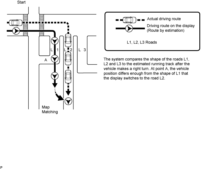
The current driving route is calculated by autonomous navigation (according to the gyro sensor and vehicle speed sensor) and GPS navigation. This information is then compared with possible road shapes from the map data in the map disc and the vehicle position is set onto the most appropriate road.