Home › ENGINE › 1NZ-FXE ENGINE CONTROL SYSTEM › SFI SYSTEM

DTC    P1450    Fuel Tank Pressure Sensor

DTC    P1451    Fuel Tank Pressure Sensor Range/Performance

DTC    P1452    Fuel Tank Pressure Sensor Low Input

DTC    P1453    Fuel Tank Pressure Sensor High Input

for Preparation Click here


DTC SUMMARY


DTC No.
Monitoring Item
DTC Detection Condition
Trouble Area
Detection Timing
Detection Logic
P1450
Pressure sensor abnormal voltage fluctuation
Fuel tank pressure rapidly fluctuates beyond upper and lower malfunction thresholds for 7 seconds.
  1. Fuel tank pressure sensor
  2. Connector/wire harness (Fuel tank pressure sensor - ECM)
  3. ECM
  1. Power switch ON (IG)
1 trip
P1451
Pressure sensor abnormal voltage fluctuation
Sensor output voltage fluctuates frequently in certain time period.
  1. Fuel tank pressure sensor
  2. Connector/wire harness (Fuel tank pressure sensor - ECM)
  3. ECM
  1. EVAP monitoring (power switch OFF)
  2. Engine running
2 trips
P1451
Pressure sensor constant voltage
Sensor output voltage does not vary in certain time period.
  1. Fuel tank pressure sensor
  2. Connector/wire harness (Fuel tank pressure sensor - ECM)
  3. ECM
  1. Engine running
2 trips
P1452
Pressure sensor voltage low
Sensor output is less than -3,999 Pa for 7 seconds.
  1. Fuel tank pressure sensor
  2. Connector/wire harness (Fuel tank pressure sensor - ECM)
  3. ECM
  1. EVAP monitoring (power switch OFF)
  2. Power switch ON (IG)
1 trip
P1453
Pressure sensor voltage high
Sensor output 1,999 Pa or more for 7 seconds.
  1. Fuel tank pressure sensor
  2. Connector/wire harness (Fuel tank pressure sensor - ECM)
  3. ECM
  1. EVAP monitoring (power switch OFF)
  2. Power switch ON (IG)
1 trip

DESCRIPTION

NOTICE:
In this vehicle's EVAP system, turning ON the vent valve does not seal off the EVAP system. To check for leaks in the EVAP system, disconnect the air inlet vent hose and apply pressure from the atmosphere side of the canister.

While the engine is running, if a predetermined condition (closed loop, etc.) is met, the purge VSV is opened by the ECM and stored fuel vapors in the canister are purged to the intake manifold. The ECM changes the duty cycle ratio of the purge VSV to control purge flow volume.
The purge flow volume is also determined by the intake manifold pressure. Atmospheric pressure is allowed into the canister through the vent valve to ensure that the purge flow is maintained when the negative pressure (vacuum) is applied to the canister.
  1. Key-off monitor
    This monitor checks for Evaporative Emission (EVAP) system leaks and canister pump module malfunctions. The monitor starts 5 hours* after the power switch is turned OFF. More than 5 hours are required to allow the fuel to cool down to stabilize the Fuel Tank Pressure (FTP), thus making the EVAP system monitor more accurate.
    The leak detection pump creates negative pressure (vacuum) in the EVAP system and the pressure is measured. Finally, the ECM monitors for leaks from the EVAP system and malfunctions in both the canister pump module and purge VSV, based on the EVAP pressure.

    HINT:
    *: If the engine coolant temperature is not below 35°C (95°F) 5 hours after the power switch is turned OFF, the monitor check starts 2 hours later. If it is still not below 35°C (95°F) 7 hours after the power switch is turned OFF, the monitor check starts 2.5 hours later.


A131350E03


A130305E03


A131438E01


A115543E13


Components
Operations
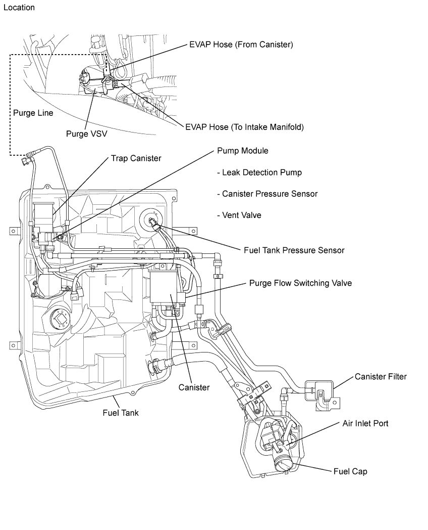
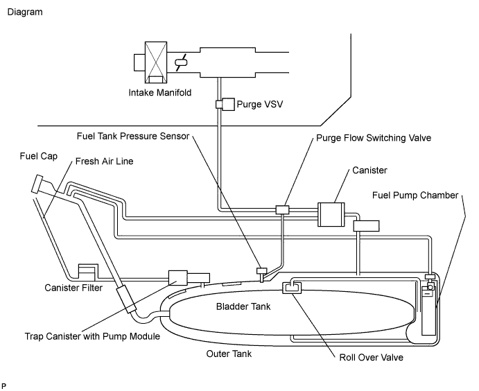
Canister, Trap canister
Contains activated charcoal to absorb EVAP generated in fuel tank.
Cut-off valve
Located in fuel tank. Valve floats and closes when fuel tank is 100% full.
Purge Vacuum Switching Valve (VSV)
Opens or closes line between canister and intake manifold. ECM uses purge VSV to control EVAP purge flow. In order to discharge EVAP absorbed by canister to intake manifold, ECM opens purge VSV. EVAP discharge volume to intake manifold controlled by purge VSV duty cycle ratio (current-carrying time) (open: ON; closed: OFF).
Roll-over valve
Located in fuel tank. Valve closes by its own weight when vehicle overturns to prevent fuel from spilling out.
Soak timer
Built into ECM. To ensure accurate EVAP monitor, measures 5 hours (+-15 min) after power switch OFF. This allows fuel to cool down, stabilizing Fuel Tank Pressure (FTP). When approximately 5 hours elapsed, ECM activates.
Purge flow switching valve
The purge flow switching valve located on the canister is used to detect leakage from the bladder tank into the fuel tank. The valve opens during the bladder tank leak check. Then, the fuel tank's fuel vapor flows to the intake manifold without passing the canister.
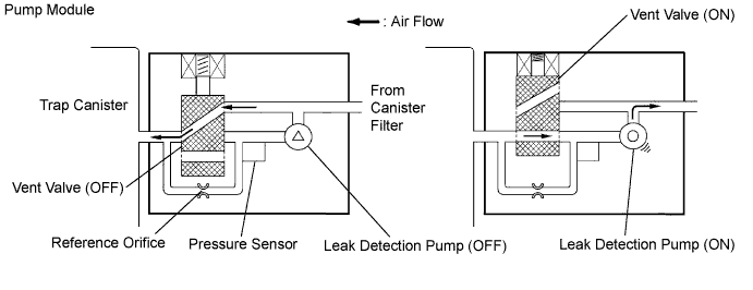
Pump module
Consists of (a) to (d) below. pump module cannot be disassembled.
(a) Vent valve
Vents and closes EVAP system. When ECM turns valve ON, EVAP system is closed. When ECM turns valve OFF, EVAP system is vented. Negative pressure (vacuum) created in EVAP system to check for EVAP leaks by closing purge VSV, turning vent valve ON (closed) and operating leak detection pump.
(b) Canister pressure sensor
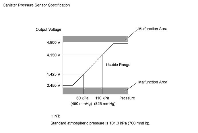
Indicates pressure as voltage. ECM supplies regulated 5 V to canister pressure sensor, and uses feedback from sensor to monitor EVAP system pressure.
(c) Leak detection pump
Creates negative pressure (vacuum) in EVAP system for leak check.
(d) Reference orifice
Has opening with 0.02 inch diameter. Vacuum produced through orifice by closing purge VSV, turning vent valve OFF and operating leak detection pump to monitor 0.02 inch leak criterion. 0.02 inch leak criterion indicates small leak of EVAP.

MONITOR DESCRIPTION


  1. DTC P1451: Pressure sensor abnormal voltage fluctuation or being constant
    If the pressure sensor output voltage fluctuates rapidly for 10 seconds, the ECM stops the EVAP system monitor. The ECM interprets this as the pressure sensor voltage fluctuating, and stops the EVAP system monitor. The ECM then illuminates the MIL and sets the DTC.
    Alternatively, if the sensor output voltage does not change for 10 seconds, the ECM interprets this as the sensor voltage being constant, and stops the monitor. The ECM then illuminates the MIL and sets the DTC.
    (Both the malfunctions are detected by 2 trip detection logic).


    A109185E04

  2. DTC P1452: Pressure sensor voltage low
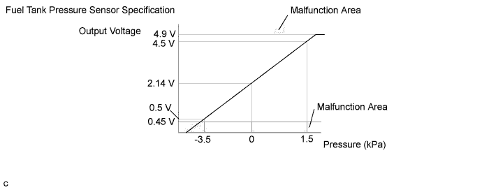
    If the pressure sensor output voltage is below 0.45 V, the ECM interprets this as an open or short circuit malfunction in the pressure sensor or its circuit, and stops the EVAP system monitor. The ECM then illuminates the MIL and sets the DTC (1 trip detection logic).
  3. DTC P1453: Pressure sensor voltage high
    If the pressure sensor voltage output is 4.9 V or more, the ECM interprets this as an open or short circuit malfunction in the pressure sensor or its circuit, and stops the EVAP system monitor. The ECM then illuminates the MIL and sets the DTC (1 trip detection logic).

MONITOR STRATEGY


Required Sensors/Components
Pump module
Frequency of Operation
Once per driving cycle: P1451 sensor constant voltage
Continuous: P1451 sensor abnormal voltage fluctuation, P1452 and P1453
Duration
Within 10 seconds
MIL Operation
2 driving cycles
Sequence of Operation
None

TYPICAL ENABLING CONDITIONS


P1450, P1452, P1453: 
Engine
Running
Time after engine start
Less than 10 seconds
ECT at engine start
10 to 35°C (50 to 95°F)
IAT at engine start
10 to 35°C (50 to 95°F)
ECT at engine start - IAT at engine start
Less than 12°C (53.6°F)

P1451: 
Altitude
Less than 2,400 m (8,000 ft.)
Battery voltage
11 V or higher
Conditions
Power switch ON (IG) and DLC3 connector OFF
or
OBD check mode ON and idle ON
Throttle position learning
Completed
Canister pressure sensor
No malfunction
IAT at engine start - ECT at engine start
-7 to 11.1°C (19.4 to 52°F)
Purge VSV and purge flow switching valve
Not operated by scan tool
ECT at engine start
4.4 to 35°C (40 to 95°F)
IAT at engine start
4.4 to 35°C (40 to 95°F)

TYPICAL MALFUNCTION THRESHOLDS


P1450: 
Fuel tank pressure
Less than -3,999 Pa (-30 mmHg) or 1,999 Pa (15 mmHg) or more

P1451 (Noise Monitor): 
Sensor output change 0.667 kPa or more during 5 to 15 seconds after idling and vehicle stop
7 times or more

P1451 (Stuck Monitor): 
Not to make pass determination
20 minutes or more

P1452: 
Fuel tank pressure
Less than -3,999 Pa (-30 mmHg)

P1453: 
Fuel tank pressure
1,999 Pa (15 mmHg) or more

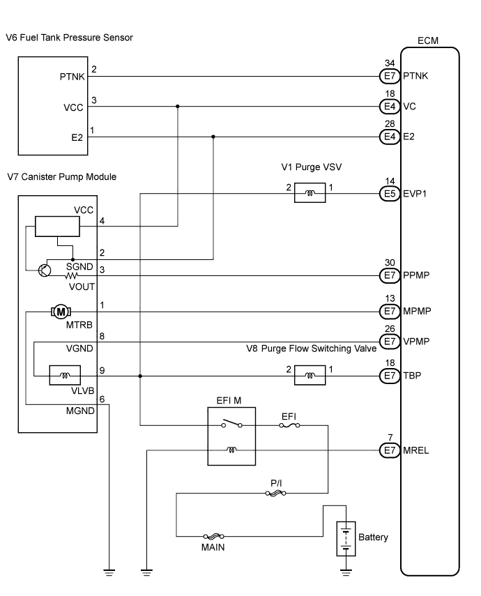
WIRING DIAGRAM


A151903E05


INSPECTION PROCEDURE

NOTICE:
  1. When a vehicle is brought into the workshop, leave it as it is. Do not change the vehicle condition. For example, do not tighten the fuel tank cap.
  1. Do not disassemble the pump module.
  1. Techstream is required to conduct the following diagnostic troubleshooting procedure.

1.CONFIRM DTC AND FUEL TANK PRESSURE
  1. Connect Techstream to the DLC3.

  1. Turn the power switch ON (IG).

  1. Turn the tester on.

  1. Enter the following menus: Powertrain / Engine and ECT / Trouble Code.

  1. Read DTCs.

  1. Enter the following menus: Powertrain / Engine and ECT / Data List / Vapor Press Tank.

  1. Read the EVAP (Evaporative Emission) pressure displayed on the tester.

    Result:

    Display (DTC Output)
    Test Result
    Suspected Trouble Area
    Proceed to
    P1451
    -
    1. Pressure sensor
    C
    P1450 and/or P1452
    Less than -17.187 kPa (-128.93 mmHg)
    1. Wire harness/connector (ECM - pressure sensor)
    2. Pressure sensor
    3. Short in ECM circuit
    A
    P1450 and/or P1453
    More than 23.5 kPa (176.69 mmHg)
    1. Wire harness/connector (ECM - pressure sensor)
    2. Pressure sensor
    3. Open in ECM circuit
    B


B
Go to step 4

C
GO TO EVAP INSPECTION PROCEDURE
A


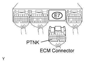
2.CHECK HARNESS AND CONNECTOR (FUEL TANK PRESSURE SENSOR - ECM)


    A065744E69
  1. Turn the power switch OFF.

  1. Disconnect the E7 ECM connector.

  1. Measure the resistance between the PTNK terminal of the ECM connector and the body ground.

    Result:

    Test Result
    Suspected Trouble Area
    Proceed to
    10 Ω or less
    1. Wire harness/connector (ECM - pressure sensor)
    2. Short in pressure sensor circuit
    A
    10 kΩ or more
    1. Wire harness/connector (ECM - pressure sensor)
    2. Short in ECM (included in HV Control ECU) circuit
    B

  1. Reconnect the ECM connector.


B
Go to step 7
A


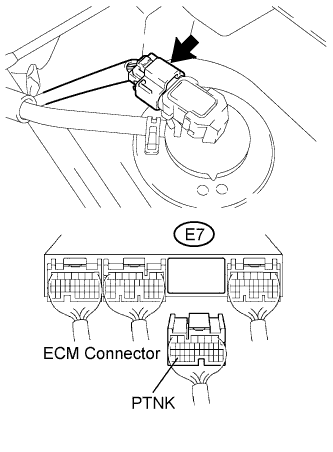
3.CHECK HARNESS AND CONNECTOR (FUEL TANK PRESSURE SENSOR - ECM)


    A131349E01
  1. Remove the fuel tank assembly.

  1. Disconnect the V6 fuel tank pressure sensor connector.

  1. Disconnect the E7 ECM connector.

  1. Measure the resistance between the PTNK terminal of the ECM connector and the body ground.

    Result:

    Test Result
    Suspected Trouble Area
    Proceed to
    10 kΩ or more
    1. Short in pressure sensor circuit
    A
    10 Ω or less
    1. Short in wire harness/connector (ECM - pressure sensor)
    B

  1. Reconnect the pressure sensor connector.

  1. Reconnect the ECM connector.


A
Go to step 5

B
Go to step 6

4.CHECK HARNESS AND CONNECTOR (FUEL TANK PRESSURE SENSOR - ECM)


    A109175E06
  1. Remove the fuel tank assembly.

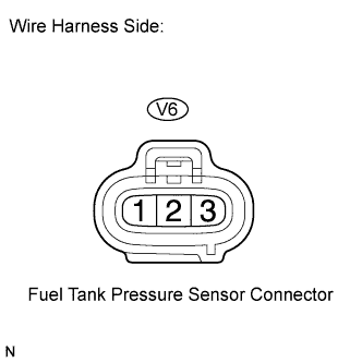
  1. Disconnect the V6 fuel tank pressure sensor connector.

  1. Turn the power switch ON (IG).

  1. Measure the voltage and resistance according to the value(s) in the table below.

    Standard voltage:
    Tester Connection
    Specified Condition
    V6-3 - Body ground
    4.5 to 5.0 V

    Standard resistance:
    Tester Connection
    Specified Condition
    V6-2 - Body ground
    100 Ω or less


    Result:

    Test Result
    Suspected Trouble Area
    Proceed to
    Voltage and resistance within standard ranges
    1. Open in pressure sensor circuit
    A
    Voltage and resistance outside standard ranges
    1. Open in wire harness/connector (ECM - pressure sensor)
    B

  1. Reconnect the canister connector.


B
Go to step 6
A


5.REPLACE FUEL TANK PRESSURE SENSOR


NEXT
Go to step 8

6.REPAIR OR REPLACE HARNESS OR CONNECTOR

HINT:
If the exhaust tail pipe has been removed, go to the next step before reinstalling it.


NEXT
Go to step 8

7.REPLACE ECM


NEXT
Go to step 8

8.CHECK WHETHER DTC OUTPUT RECURS (AFTER REPAIR)
  1. Connect Techstream to the DLC3.

  1. Turn the power switch ON (IG) and turn the tester on.

  1. Wait for at least 60 seconds.

  1. Enter the following menus: Powertrain / Engine and ECT / Trouble Code / Pending.

    HINT:
    If no pending DTC is displayed on the tester, the repair has been successfully completed.


NEXT

COMPLETED