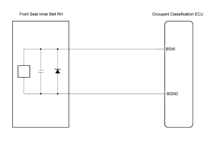
DTC B1771 Passenger Side Buckle Switch Circuit Malfunction |
| DTC No. | DTC Detection Condition | Trouble Area |
| B1771 | When one of following conditions is met:
|
|
| 1.CHECK FOR DTC |
Turn the power switch ON (IG).
Clear the DTCs (Click here).
Turn the power switch OFF.
Turn the power switch ON (IG).
Check the DTCs (Click here).
|
| ||||
| NG | |
 |
| 2.CHECK CONNECTION OF CONNECTOR |
Turn the power switch OFF.
Disconnect the cable from the negative (-) battery terminal, and wait for at least 90 seconds.
Check that the connectors are properly connected to the occupant classification ECU and the front seat inner belt RH.
|
| ||||
| OK | |
|
| 3.CHECK FLOOR WIRE NO. 2 (TO B+) |
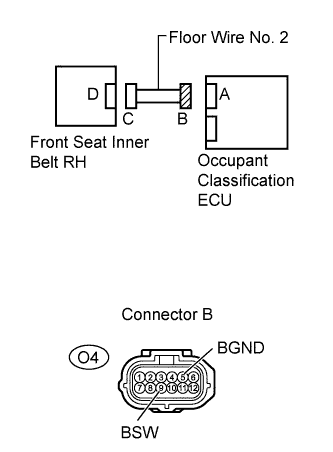 |
Disconnect the connectors from the occupant classification ECU and the front seat inner belt RH.
Connect the cable to the negative (-) battery terminal, and wait for at least 2 seconds.
Turn the power switch ON (IG).
Measure the voltage of the wire harness side connector.
| Tester Connection | Specified Condition |
| O4-9 (BSW) - Body ground | Below 1 V |
| O4-5 (BGND) - Body ground | Below 1 V |
|
| ||||
| OK | |
|
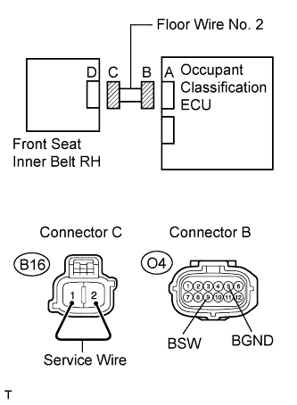
| 4.CHECK FLOOR WIRE NO. 2 (FOR OPEN) |
 |
Turn the power switch OFF.
Disconnect the cable from the negative (-) battery terminal, and wait for at least 90 seconds.
Using a service wire, connect terminals B16-2 and B16-1 of connector C.
Measure the resistance of the wire harness side connector.
| Tester Connection | Specified Condition |
| O4-9 (BSW) - O4-5 (BGND) | Below 1 Ω |
|
| ||||
| OK | |
|
| 5.CHECK FLOOR WIRE NO. 2 (FOR SHORT) |
|
Disconnect the service wire from connector C.
Measure the resistance of the wire harness side connector.
| Tester Connection | Specified Condition |
| O4-9 (BSW) - O4-5 (BGND) | 1 MΩ or higher |
|
| ||||
| OK | |
|
| 6.CHECK FLOOR WIRE NO. 2 (TO GROUND) |
|
Measure the resistance of the wire harness side connector.
| Tester Connection | Specified Condition |
| O4-9 (BSW) - Body ground | 1 MΩ or higher |
| O4-5 (BGND) - Body ground | 1 MΩ or higher |
|
| ||||
| OK | |
|
| 7.CHECK FOR DTC |
Connect the connectors to the occupant classification ECU and the front seat inner belt RH.
Connect the cable to the negative (-) battery terminal, and wait for at least 2 seconds.
Turn the power switch ON (IG).
Clear the DTCs (Click here).
Turn the power switch OFF.
Turn the power switch ON (IG).
Check the DTCs (Click here).
|
| ||||
| NG | |
|
| 8.REPLACE FRONT SEAT INNER BELT ASSEMBLY RH |
Turn the power switch OFF.
Disconnect the cable from the negative (-) battery terminal, and wait for at least 90 seconds.
Replace the front seat inner belt RH (Click here).
Connect the cable to the negative (-) battery terminal, and wait for at least 2 seconds.
Turn the power switch ON (IG).
Clear the DTCs (Click here).
Turn the power switch OFF.
Turn the power switch ON (IG).
Check the DTCs (Click here).
|
| ||||
| NG | |
|
| 9.REPLACE OCCUPANT CLASSIFICATION ECU |
Turn the power switch OFF.
Disconnect the cable from the negative (-) battery terminal, and wait for at least 90 seconds.
Replace the occupant classification ECU.
| NEXT | |
|
| 10.PERFORM ZERO POINT CALIBRATION |
Connect the cable to the negative (-) battery terminal, and wait for at least 2 seconds.
Connect the Techstream to the DLC3.
Turn the power switch ON (IG).
Using the Techstream, perform the zero point calibration (Click here).
| NEXT | |
|
| 11.PERFORM SENSITIVITY CHECK |
Using the Techstream, perform the sensitivity check (Click here).
| NEXT | ||
 | ||
| ||
