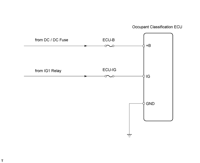
DTC B1795 Occupant Classification ECU Malfunction |
| DTC No. | DTC Detection Condition | Trouble Area |
| B1795 | When one of following conditions is met:
|
|
| 1.CHECK FOR DTC |
Turn the power switch ON (IG), and wait for at least 10 seconds.
Check the DTCs (Click here).
| Result | Proceed to |
| DTC B1795 is output. | A |
| DTC B1771 and B1795 are output. | B |
|
| ||||
| A | |
 |
| 2.CHECK FUSE (ECU-B) |
Check the ECU-B fuse from the instrument panel junction block.
Measure the resistance of the fuse.
|
| ||||
| OK | |
|
| 3.CHECK WIRE HARNESS (SOURCE VOLTAGE) |
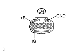 |
Turn the power switch OFF.
Disconnect the cable from the negative (-) battery terminal, and wait for at least 90 seconds.
Disconnect the floor wire No. 2 connector from the occupant classification ECU.
Connect the cable to the negative (-) battery terminal, and wait for at least 2 seconds.
Measure the voltage of the wire harness side connector.
| Tester Connection | Condition | Specified Condition |
| O4-1 (+B) - Body ground | Always | 10 to 14 V |
| O4-7 (IG) - Body ground | Power switch ON (IG) | 10 to 14 V |
Turn the power switch OFF.
Measure the resistance of the wire harness side connector.
| Tester Connection | Specified Condition |
| O4-3 (GND) - Body ground | Below 1 Ω |
|
| ||||
| OK | |
|
| 4.REPLACE OCCUPANT CLASSIFICATION ECU |
Turn the power switch OFF.
Disconnect the cable from the negative (-) battery terminal, and wait for at least 90 seconds.
Replace the occupant classification ECU.
| NEXT | |
|
| 5.PERFORM ZERO POINT CALIBRATION |
Connect the cable to the negative (-) battery terminal, and wait for at least 2 seconds.
Connect the Techstream to the DLC3.
Turn the power switch ON (IG).
Using the Techstream, perform the zero point calibration (Click here).
| NEXT | |
|
| 6.PERFORM SENSITIVITY CHECK |
Using the Techstream, perform the sensitivity check (Click here).
| NEXT | ||
 | ||
| ||
