Home › MAINTENANCE › MAINTENANCE › ENGINE

ENGINE > GENERAL MAINTENANCE


1. INSPECT DRIVE BELT


    A087786E01
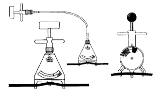
  1. Using a belt tension gauge, measure the belt tension.
    Belt tension gauge:
    DENSO BTG-20 (95506-00020)
    Borroughs No. BT-33-73F

    Standard drive belt tension:
    Item
    Specified Condition
    New belt
    99 to 121 lbf
    Used belt
    55 to 77lbf


    HINT:
    A122295E01
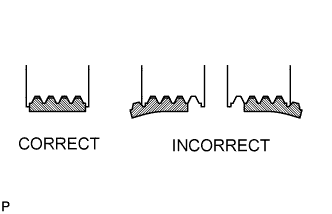
    1. After installing the drive belt, check that it fits properly in the ribbed grooves. Check with your hands to confirm that the belt has not slipped out of the groove on the bottom of the crankshaft pulley.
    2. A "new belt" is a belt which has been used less than 5 minutes on a running engine.
    3. A "used belt" is a belt which has been used on a running engine for 5 minutes or more.
    4. After installing a new belt, run the engine for approximately 5 minutes and then recheck the tension.
  1. Reference:
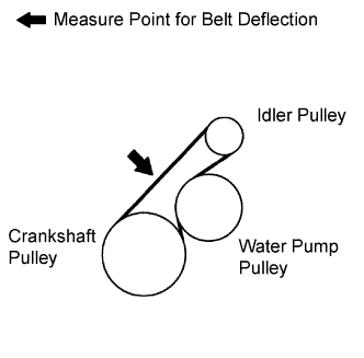
    Check the drive belt deflection.


      A093818E02
    1. When not using a belt tension gauge, measure the belt deflection.
      Pressing force: 98 N (10 kgf, 22 lbf)

      Standard belt deflection:
      Item
      Specified Condition
      New belt
      9.0 to 12.0 mm (0.35 to 0.47 in.)
      Used belt
      11 to 15 mm (0.43 to 0.59 in.)

      NOTICE:
      1. Check the drive belt deflection at the specified point.
      2. When installing a new belt, set its tension value as specified.
      3. When inspecting a belt which has been used over 5 minutes, apply the specification for "Used belt".
      4. When reinstalling a belt which has been used over 5 minutes, adjust its deflection and tension to the intermediate value of each specification for "Used belt".
      5. Belt tension and deflection should be checked after 2 revolutions of engine cranking.
      6. When using a belt tension gauge, confirm the accuracy by using a master gauge first.


2. REPLACE SPARK PLUGS
  1. Replace the spark plugs .


3. REPLACE AIR CLEANER FILTER
  1. Remove the air filter.

  1. Visually check that the air filter is not excessively damaged or oily.

  1. Replace the air filter with a new one, if necessary.


4. REPLACE ENGINE OIL AND OIL FILTER
  1. Warm up the engine, then stop the engine and wait for 5 minutes. Check that the engine oil level is between the low and full marks on the oil level gauge.
    If the engine oil is low, check for oil leaks and add engine oil up to the full mark.

    NOTICE:
    Do not add engine oil above the full mark.


5. REPLACE ENGINE COOLANT
  1. The engine coolant should be between the low and full lines when the engine is cold.
    If low, check for leaks and add TOYOTA Super Long Life Coolant (SLLC) or similar high quality ethylene glycol based non-silicate, non-amine, non-nitrite, non-borate coolant with long-life hybrid organic acid technology up to the full line.

    NOTICE:
    Never use water as a substitute for engine coolant.


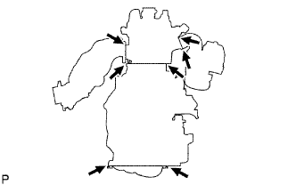
6. INSPECT GASKET IN FUEL TANK CAP


A087597E01
  1. Check the appearance.

    1. Visually check that there are no cracks, leaks or damage on the indicated portions in the illustration.

      HINT:
      1. Removing the oil level gauge, oil filler cap or ventilation hoses may cause the engine malfunction or engine stall.
      2. If the parts between the mass air flow meter and cylinder head are disconnected, loose or cracked, secondary air may be sucked. If could cause the engine malfunction or engine stall.


7. INSPECT FUEL LINES AND CONNECTIONS, FUEL TANK VAPOR VENT SYSTEM HOSES
  1. Visually check the fuel lines for cracks, leakage, loose connections and deformation.


8. INSPECT EXHAUST PIPES AND MOUNTINGS
  1. Visually check the pipes, hangers and connections for severe corrosion, leaks or damage.


9. INSPECT VALVE CLEARANCE

HINT:
Inspect and adjust the valve clearance when the engine is cold.


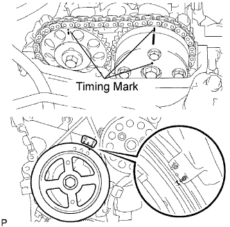
    A092837E01
  1. Set the No. 1 cylinder to TDC/compression.

    1. Turn the crankshaft pulley until its timing notch and timing mark 0 of the chain cover are aligned.

    2. Check that both timing marks on the camshaft timing sprocket and camshaft timing gear are facing upward as shown in the illustration.
      If not, turn the crankshaft 1 complete revolution (360°) and align the marks as above.


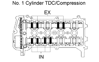
    A081895E02
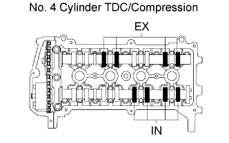
  1. Check the valves indicated in the illustration.

    1. Using a feeler gauge, measure the clearance between the valve lifter and camshaft.

      Standard valve clearance (Cold):
      Item
      Specified Condition
      Intake
      0.17 to 0.23 mm (0.007 to 0.009 in.)
      Exhaust
      0.27 to 0.33 mm (0.011 to 0.013 in.)

    2. Record any out-of-specification valve clearance measurements. They will be used later to determine the required replacement adjusting shim.

  1. Turn the crankshaft 1 complete revolution until its timing notch and timing mark 0 of the chain cover are aligned.


    A081896E02
  1. Check the valves indicated in the illustration.

    1. Using a feeler gauge, measure the clearance between the valve lifter and camshaft.

      Standard valve clearance (Cold):
      Item
      Specified Condition
      Intake
      0.17 to 0.23 mm (0.007 to 0.009 in.)
      Exhaust
      0.27 to 0.33 mm (0.011 to 0.013 in.)

    2. Record any out-of-specification valve clearance measurements. They will be used later to determine the required replacement adjusting shim.