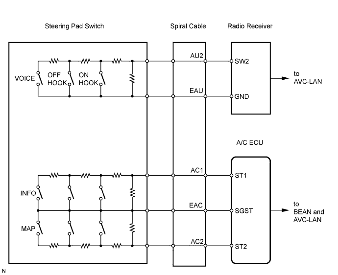
NAVIGATION SYSTEM > Steering Pad Switch Circuit |
| 1.INSPECT STEERING PAD SWITCH ASSEMBLY |
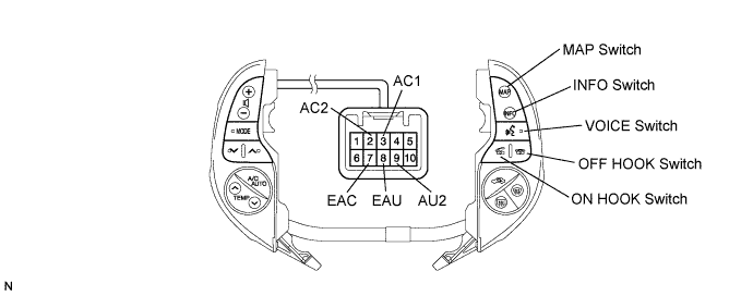
Disconnect the switch connector.
Measure the resistance of the switch.
| Tester connection | Condition | Specified condition |
| 9 (AU2) - 8 (EAU) | No switch is pushed | 100 kΩ or higher |
| 9 (AU2) - 8 (EAU) | VOICE switch pushed | 3,110 Ω |
| 9 (AU2) - 8 (EAU) | ON HOOK switch pushed | 329 Ω |
| 9 (AU2) - 8 (EAU) | OFF HOOK switch pushed | 1,000 Ω |
| 3 (AC1) - 7 (EAC) | Not pushed | 30 kΩ or higher |
| 3 (AC1) - 7 (EAC) | INFO switch pushed | 3,062 Ω |
| 2 (AC2) - 7 (EAC) | Not pushed | 30 kΩ or higher |
| 2 (AC2) - 7 (EAC) | MAP switch pushed | 3,062 Ω |
|
| ||||
| OK | |
 |
| 2.INSPECT SPIRAL CABLE |
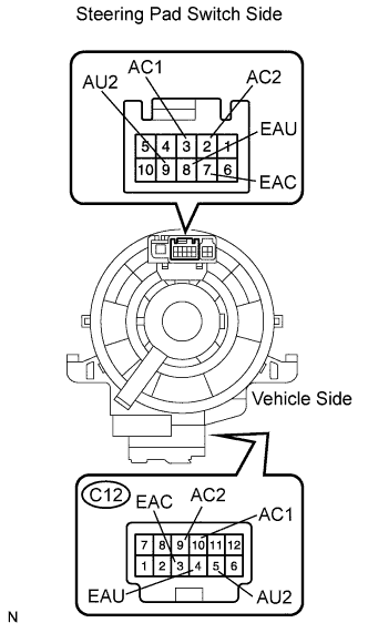 |
Disconnect the cable connectors.
Measure the resistance of the cable.
| Tester connection | Spiral Cable Position | Specified condition |
| C12-4 (EAU) - 8 (EAU) | Center | Below 1 Ω |
| 2.5 rotations to the left | ||
| 2.5 rotations to the right | ||
| C12-5 (AU2) - 9 (AU2) | Center | Below 1 Ω |
| 2.5 rotations to the left | ||
| 2.5 rotations to the right | ||
| C12-3 (EAC) - 7 (EAC) | Center | Below 1 Ω |
| 2.5 rotations to the left | ||
| 2.5 rotations to the right | ||
| C12-9 (AC2) - 2 (AC2) | Center | Below 1 Ω |
| 2.5 rotations to the left | ||
| 2.5 rotations to the right | ||
| C12-10 (AC1) - 3 (AC1) | Center | Below 1 Ω |
| 2.5 rotations to the left | ||
| 2.5 rotations to the right |
|
| ||||
| OK | |
|
| 3.CHECK WIRE HARNESS (SPIRAL CABLE - RADIO RECEIVER) |
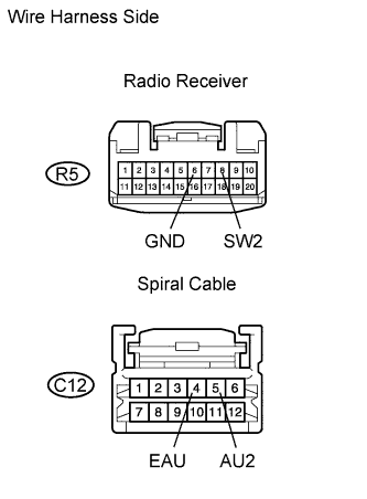 |
Disconnect the R5 receiver connector.
Disconnect the C12 cable connector.
Measure the resistance of the wire harness side connectors.
| Tester Connection | Specified Condition |
| R5-8 (SW2) - C12-5 (AU2) | Below 1 Ω |
| R5-6 (GND) - C12-4 (EAU) | Below 1 Ω |
| R5-8 (SW2) - Body ground | 10 kΩ or higher |
| R5-6 (GND) - Body ground | 10 kΩ or higher |
|
| ||||
| OK | |
|
| 4.CHECK WIRE HARNESS (SPIRAL CABLE - AIR CONDITIONING AMPLIFIER) |
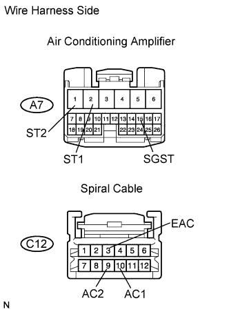 |
Disconnect the A7 amplifier connector.
Disconnect the C12 cable connector.
Measure the resistance of the wire harness side connectors.
| Tester Connection | Specified Condition |
| A7-2 (ST1) - C12-10 (AC1) | Below 1 Ω |
| A7-15 (SGST) - C12-3 (EAC) | Below 1 Ω |
| A7-1 (ST2) - C12-9 (AC2) | Below 1 Ω |
| A7-2 (ST1) - Body ground | 10 kΩ or higher |
| A7-15 (SGST) - Body ground | 10 kΩ or higher |
| A7-1 (ST2) - Body ground | 10 kΩ or higher |
|
| ||||
| OK | ||
 | ||
| ||
