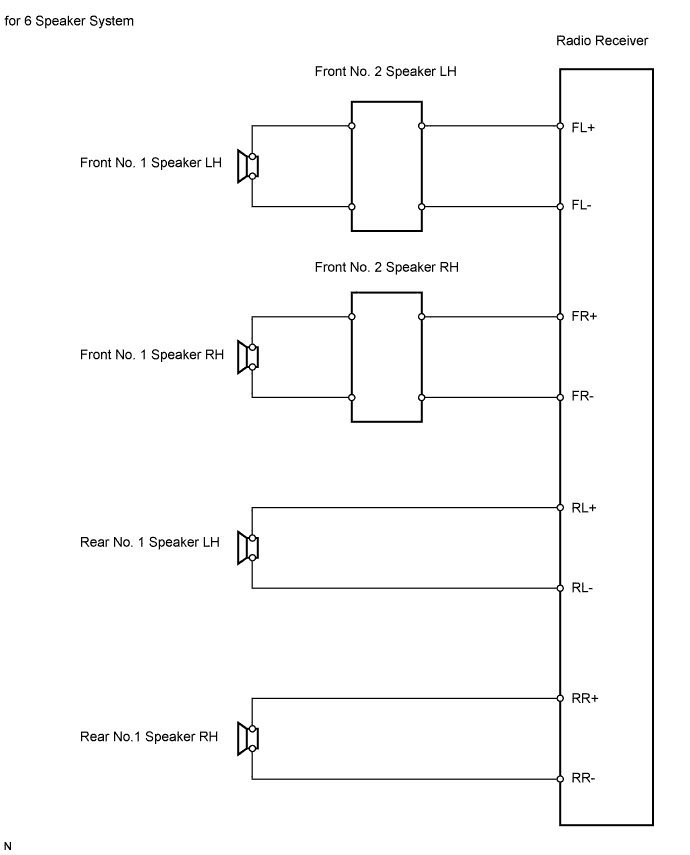
AUDIO AND VISUAL SYSTEM > Speaker Circuit |
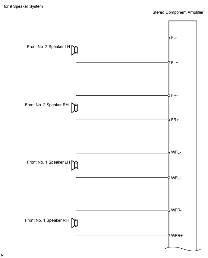
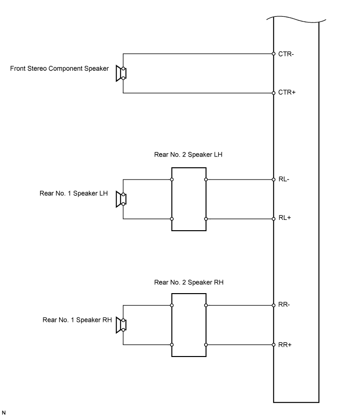
| 1.CHECK VEHICLE EQUIPMENT |
| Vehicle equipment | Proceed to |
| 6 speaker system | A |
| 9 speaker system | B |
|
| ||||
| A | |
 |
| 2.CHECK WIRE HARNESS (RADIO RECEIVER - SPEAKER) |
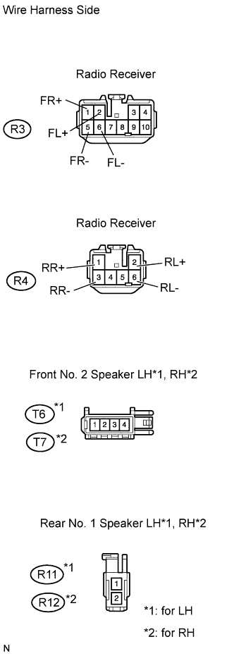 |
Disconnect the R3 and R4 receiver connectors.
Disconnect the T6, T7, R11 and R12 speaker connectors.
Measure the resistance of the wire harness side connectors.
| Tester Connection | Specified Condition |
| R3-2 (FL+) - T6-4 | Below 1 Ω |
| R3-6 (FL-) - T6-2 | Below 1 Ω |
| R3-1 (FR+) - T7-4 | Below 1 Ω |
| R3-5 (FR-) - T7-2 | Below 1 Ω |
| R4-2 (RL+) - R11-1 | Below 1 Ω |
| R4-6 (RL-) - R11-2 | Below 1 Ω |
| R4-1 (RR+) - R12-1 | Below 1 Ω |
| R4-3 (RR-) - R12-2 | Below 1 Ω |
|
| ||||
| OK | |
|
| 3.CHECK WIRE HARNESS (FRONT NO. 1 SPEAKER - FRONT NO. 2 SPEAKER) |
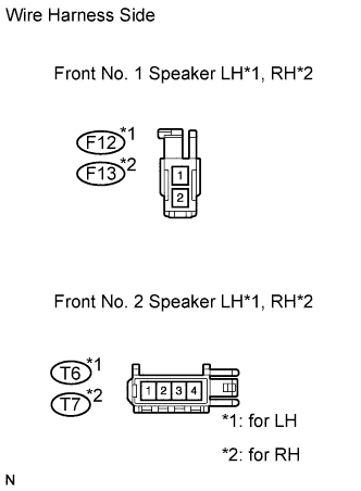 |
Disconnect the F12, F13, T6 and T7 speaker connectors.
Measure the resistance of the wire harness side connectors.
| Tester Connection | Specified Condition |
| F12-1 - T6-3 | Below 1 Ω |
| F12-2 - T6-1 | Below 1 Ω |
| F13-1 - T7-3 | Below 1 Ω |
| F13-2 - T7-1 | Below 1 Ω |
|
| ||||
| OK | |
|
| 4.INSPECT FRONT NO. 1 SPEAKER |
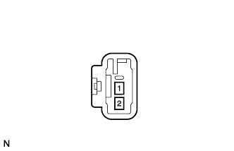 |
Disconnect the F12 and F13 speaker connectors.
Measure the resistance of the speaker.
| Tester Connection | Specified Condition |
| 1 - 2 | Approximately 4 Ω |
|
| ||||
| OK | |
|
| 5.INSPECT FRONT NO. 2 SPEAKER |
Check that the malfunction disappears when the speaker is replaced with a normal one.
|
| ||||
| OK | |
|
| 6.INSPECT REAR NO. 1 SPEAKER |
|
Disconnect the R11 and R12 speaker connectors.
Measure the resistance of the speaker.
| Tester Connection | Specified Condition |
| 1 - 2 | Approximately 4 Ω |
|
| ||||
| OK | ||
 | ||
| ||
| 7.CHECK WIRE HARNESS (STEREO COMPONENT AMPLIFIER - SPEAKER) |
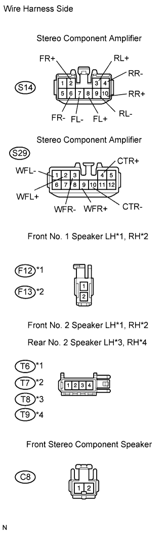 |
Disconnect the S14 and S29 amplifier connectors.
Disconnect the C8, F12, F13, T6, T7, T8 and T9 speaker connectors.
Measure the resistance of the wire harness side connectors.
| Tester Connection | Specified Condition |
| S29-2 (WFL+) - F12-1 | Below 1 Ω |
| S29-1 (WFL-) - F12-2 | Below 1 Ω |
| S29-9 (WFR+) - F13-1 | Below 1 Ω |
| S29-3 (WFR-) - F13-2 | Below 1 Ω |
| S14-8 (FL+) - T6-4 | Below 1 Ω |
| S14-7 (FL-) - T6-2 | Below 1 Ω |
| S14-2 (FR+) - T7-4 | Below 1 Ω |
| S14-6 (FR-) - T7-2 | Below 1 Ω |
| S14-3 (RL+) - T8-4 | Below 1 Ω |
| S14-9 (RL-) - T8-2 | Below 1 Ω |
| S14-10 (RR+) - T9-4 | Below 1 Ω |
| S14-4 (RR-) - T9-2 | Below 1 Ω |
| S29-4 (CTR+) - C8-2 | Below 1 Ω |
| S29-10 (CTR-) - C8-1 | Below 1 Ω |
|
| ||||
| OK | |
|
| 8.CHECK WIRE HARNESS (REAR NO. 1 SPEAKER - REAR NO. 2 SPEAKER) |
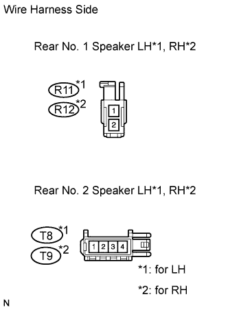 |
Disconnect the R11, R12, T8 and T9 speaker connectors.
Measure the resistance of the wire harness side connectors.
| Tester Connection | Specified Condition |
| R11-1 - T8-3 | Below 1 Ω |
| R11-2 - T8-1 | Below 1 Ω |
| R12-1 - T9-3 | Below 1 Ω |
| R12-2 - T9-1 | Below 1 Ω |
|
| ||||
| OK | |
|
| 9.INSPECT FRONT NO. 1 SPEAKER |
|
Disconnect the F12 and F13 speaker connectors.
Measure the resistance of the speaker.
| Tester Connection | Specified Condition |
| 1 - 2 | Approximately 4 Ω |
|
| ||||
| OK | |
|
| 10.INSPECT FRONT NO. 2 SPEAKER |
Check that the malfunction disappears when the speaker is replaced with a normal one.
|
| ||||
| OK | |
|
| 11.INSPECT REAR NO. 1 SPEAKER |
|
Disconnect the R11 and R12 speaker connectors.
Measure the resistance of the speaker.
| Tester Connection | Specified Condition |
| 1 - 2 | Approximately 4 Ω |
|
| ||||
| OK | |
|
| 12.INSPECT REAR NO. 2 SPEAKER |
Check that the malfunction disappears when the speaker is replaced with a normal one.
|
| ||||
| OK | |
|
| 13.INSPECT FRONT STEREO COMPONENT SPEAKER |
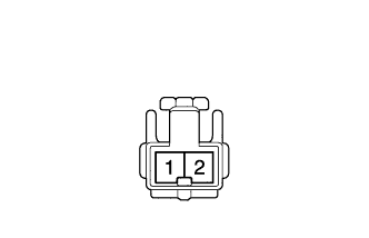 |
Disconnect the C8 speaker connector.
Measure the resistance of the speaker.
| Tester Connection | Specified Condition |
| 1 - 2 | 1.2 to 2.2 Ω |
|
| ||||
| OK | ||
| ||
| ||

