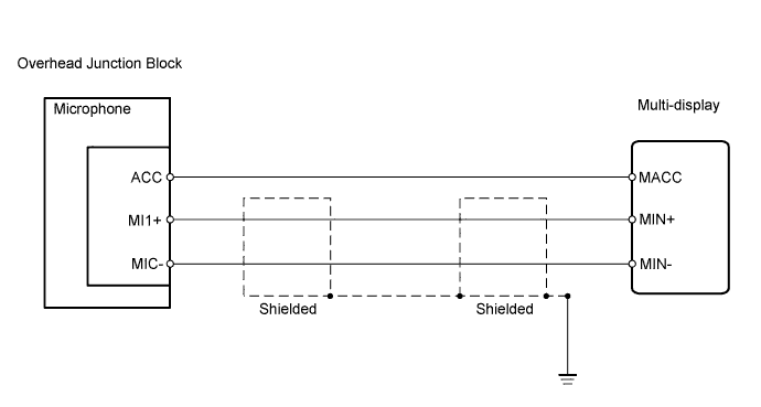
NAVIGATION SYSTEM > Microphone Circuit between Overhead J/B and Multi-display |
| 1.CHECK MULTI-DISPLAY (MACC VOLTAGE) |
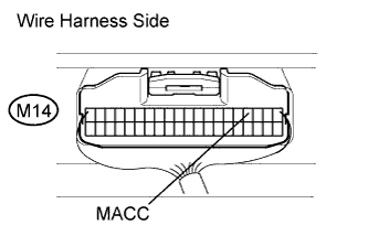 |
Measure the voltage of the display.
| Tester Connection | Condition | Specified Condition |
| M14-4 (MACC) - Body ground | Power switch ON (ACC) | 4 to 6 V |
|
| ||||
| OK | |
 |
| 2.CHECK WIRE HARNESS (MULTI-DISPLAY - OVERHEAD JUNCTION BLOCK) |
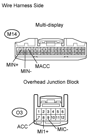 |
Disconnect the M14 display connector.
Disconnect the O3 junction block connector.
Measure the resistance of the wire harness side connectors.
| Tester Connection | Specified Condition |
| M14-4 (MACC) - O3-7 (ACC) | Below 1 Ω |
| M14-2 (MIN+) - O3-8 (MI1+) | Below 1 Ω |
| M14-3 (MIN-) - O3-9 (MIC-) | Below 1 Ω |
| M14-4 (MACC) - Body ground | 10 kΩ or higher |
| M14-2 (MIN+) - Body ground | 10 kΩ or higher |
| M14-3 (MIN-) - Body ground | 10 kΩ or higher |
|
| ||||
| OK | ||
 | ||
| ||
