Engineers must undergo special training to be able to perform high-voltage system inspection and servicing.
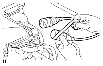
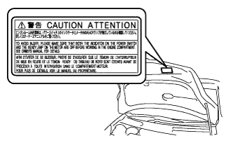
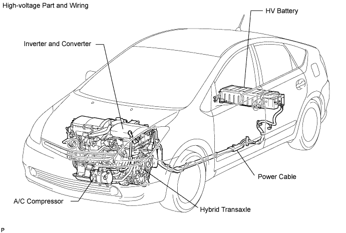
All high-voltage wire harness connectors are colored orange. The HV battery and other high-voltage components have "High Voltage" caution labels. Do not carelessly touch these wires and components.
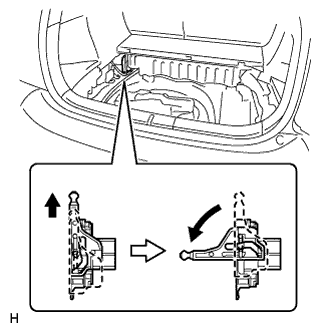
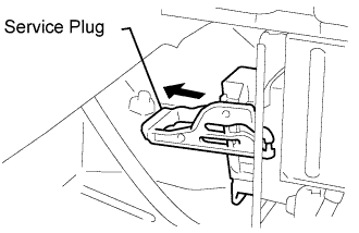
Before inspecting or servicing the high-voltage system, be sure to follow safety measures, such as wearing insulated gloves and removing the service plug to prevent electrocution. Carry the removed service plug in your pocket to prevent other technicians from reinstalling it while you are servicing the vehicle.
After removing the service plug, wait 5 minutes before touching any of the high-voltage connectors and terminals.
- HINT:
- 5 minutes are required to discharge the high-voltage condenser inside the inverter.
Be sure to install the service plug before starting the hybrid system. Starting the hybrid system with the service plug removed may damage the vehicle.
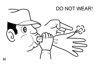
Before wearing insulated gloves, make sure that they are not cracked, ruptured, torn, or damaged in any way. Do not wear wet insulated gloves.
When servicing the vehicle, do not carry metal objects like mechanical pencils or scales that can be dropped accidentally and cause a short circuit.
Before touching a bare high-voltage terminal, wear insulated gloves and use an electrical tester to ensure that the terminal is not charged with electricity (approximately 0 V).
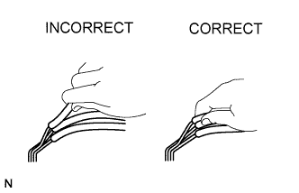
After disconnecting or exposing a high-voltage connector or terminal, insulate it immediately using insulation tape.
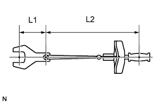
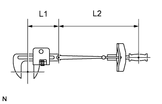
The screw of a high-voltage terminal should be tightened firmly to the specified torque. Both insufficient and excessive torque can cause failure.
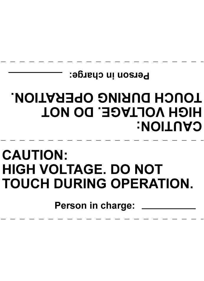
Use the "CAUTION: HIGH VOLTAGE. DO NOT TOUCH DURING OPERATION." sign to notify other engineers that a high-voltage system is being inspected and/or repaired.
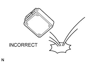
Do not place the battery upside down while removing and installing it.
After servicing the high-voltage system and before reinstalling the service plug, check again that you have not left a part or tool inside, that the high-voltage terminal screws are firmly tightened, and that the connectors are correctly connected.
Items to be prepared for operation at the site of the accident
- Protective clothing (insulated gloves, rubber gloves, goggles, and safety shoes)
- Saturated boric acid solution 20 L (obtain 800 g of boric acid powder, put it into a container, and dissolve it in water)
- Red litmus paper
- ABC fire extinguisher (effective against both oil flames and electrical flames)
- Shop rags (for wiping off the electrolyte)
- Vinyl tape (for insulating cable)
- Electrical tester
Actions to be taken at the accident site
Wear insulated or rubber gloves, goggles and safety shoes.
Do not touch a bare cable that could be a high voltage cable. If the cable must be touched or if accidental contact is unavoidable, follow these instructions: 1) wear insulated or rubber gloves and goggles, 2) measure the voltage between the cable and the body ground using an electrical tester, and 3) insulate the cable using vinyl tape.
If the vehicle catches on fire, use an ABC fire extinguisher to extinguish the fire. Trying to extinguish a fire using only a small amount of water can be more dangerous than effective. Use a substantial amount of water or wait for firefighters.
Visually check the HV battery and immediate area for any electrolyte leakage. Do not touch any leaked liquid because it could be a highly alkaline electrolyte. Wear rubber gloves and goggles, and then apply red litmus paper to the leak. If the paper turns blue, the liquid must be neutralized before wiping. Neutralize the liquid using the following procedures: 1) apply saturated boric acid solution to the liquid, and 2) reapply red litmus paper and make sure it does not turn blue. Repeat steps 1 and 2 above until the paper does not turn blue. Then, wipe the neutralized liquid with a shop rag.
If damage to any of the high-voltage components and cables is suspected, cut the high-voltage circuit using the procedure below.
- Push the "P" position switch and engage the parking brake.
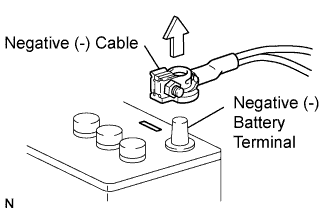
- Remove the key from the key slot. Then disconnect the negative (-) terminal of the auxiliary battery.
- Remove the service plug while wearing insulated gloves.
- CAUTION:
- Do not turn the power switch on while removing the service plug.
- NOTICE:
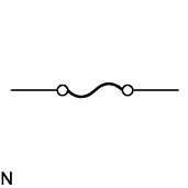
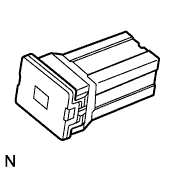
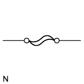
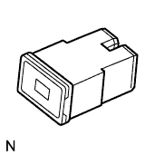
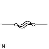
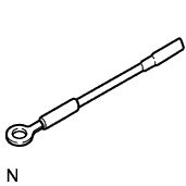
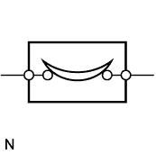
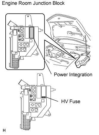
- If the service plug cannot be removed due to damage to the rear portion of the vehicle, remove the HV fuse or power integration (IGCT relay) instead.
Moving the damaged vehicle
- HINT:
- If any of the following applies, tow the vehicle away using a tow truck.
- One or more of the high-voltage components and cables are damaged.
- The driving, traction, or fuel system is damaged.
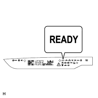
- The READY light is not illuminated when you start the engine.
- NOTICE:
- Before towing the vehicle away using a tow truck, disconnect the cable from the negative (-) terminal of the auxiliary battery and remove the service plug. Only if none of the above applies and there are no problems that might affect driving, drive the vehicle away from the accident site to a safe place nearby.
- Perform the procedure below if the READY light turns off, or there are abnormal noises, unusual smells, or strong vibrations while driving:
- Park the vehicle in a safe place.
- Push the "P" position switch and engage the parking brake.
- Disconnect the power cable from the negative (-) terminal of the auxiliary battery.
- Remove the service plug while wearing insulated gloves.
Actions required after moving the damaged vehicle If you see any liquid on the road surface, it could be a highly alkaline electrolyte leakage.
Wear rubber gloves and goggles, and apply red litmus paper to the leak. If the paper turns blue, the liquid must be neutralized before wiping. Neutralize the liquid using the following procedures: 1) apply saturated boric acid solution to the liquid, and 2) reapply red litmus paper and make sure it does not turn blue. Repeat steps 1 and 2 above until the paper does not turn blue. Then wipe the neutralized liquid with a shop rag.
Items to be prepared (when repairing damaged vehicles)
- Protective clothing (insulated gloves, rubber gloves, goggles, and safety shoes)
- Saturated boric acid solution 20 L (obtain 800 g of boric acid powder, put it into a container, and dissolve it in water)
- Red litmus paper
- Shop rags (for wiping off the electrolyte)
- Vinyl tape (for insulating cable)
- Electrical tester
Precautions to be observed when servicing the damaged vehicle
Wear insulated or rubber gloves, goggles, and safety shoes.
Do not touch a bare cable that could be a high voltage cable. If the cable must be touched or if accidental contact is unavailable, follow these instructions: 1) wear insulated or rubber gloves and goggles, 2) measure the voltage between the cable and the body ground using an electrical tester, and 3) insulate the cable using vinyl tape.
Check the HV battery and immediate area for any electrolyte leakage. Do not touch any leaked liquid because it could be a highly alkaline electrolyte. Wear rubber gloves and goggles, and then apply red litmus paper to the leak. If the paper turns blue, the liquid must be neutralized before wiping. Neutralize the liquid using the following procedures:
1) apply saturated boric acid solution to the liquid, and 2) reapply red litmus paper and make sure it does not turn blue. Repeat steps 1 and 2 above until the paper does not turn blue. Then wipe the neutralized liquid with a shop rag.
If the electrolyte adheres to your skin, wash the skin immediately using saturated boric acid solution or a large amount of water. If the electrolyte adheres to an article of clothing, take the clothing off immediately.
If the electrolyte comes in contact with your eyes, call out loudly for help. Do not rub your eyes. Wash them with a large amount of water and seek medical care immediately.
If damage to any of the high-voltage components and cables is suspected, cut the high-voltage circuit using the procedure below.
- Push the "P" position switch and engage the parking brake.
- Remove the key from the key slot. Then disconnect the power cable from the negative (-) terminal of the auxiliary battery.
- Wear insulated gloves, and then remove the service plug.
- NOTICE:
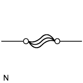
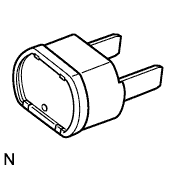
- If you cannot remove the service plug due to damage to the rear portion of the vehicle, remove the HV fuse or IGCT relay instead.
Precautions to be taken when disposing of the vehicle
When scrapping the vehicle, remove the HV battery from the vehicle and return it to the location specified by the manufacturer. The same applies to any damaged HV battery.
After removing the battery, keep it away from water. Water may heat the battery, which results in fire.
Precautions to be observed when towing
Tow the damaged vehicle with its front wheels or its front and rear wheels lifted off the ground.
- NOTICE:
- Towing the damaged vehicle with its front wheels on the ground may cause the motor to generate electricity. This electricity could, depending on the nature of the damage, leak and cause a fire.
Towing with 4 wheels on the ground
- NOTICE:
- If the damaged vehicle needs to be towed using a rope, do not exceed 30 km/h and tow only for very short distances. For example, towing from the accident site to a nearby tow truck is permissible.
- Change the power switch's power mode to ON (IG) and shift the selector lever to the N position.
- If any abnormality is present in the damaged vehicle during towing, stop towing immediately.
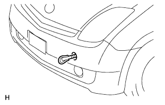
Towing eyelet
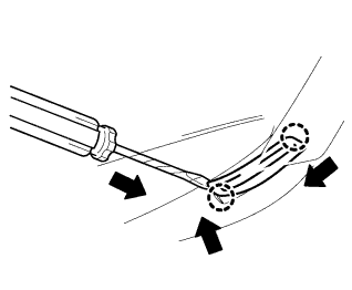
Install the hook.
Hook a rope on to the illustrated area for towing.