 |
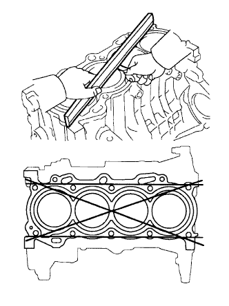
Using a precision straightedge and feeler gauge, measure the surface that is in contact with the cylinder head gasket for warpage.
- Maximum warpage:
- 0.05 mm (0.0020 in.)
ENGINE UNIT > INSPECTION |
| 1. INSPECT CYLINDER BLOCK FOR FLATNESS |
|
Using a precision straightedge and feeler gauge, measure the surface that is in contact with the cylinder head gasket for warpage.
| 2. INSPECT CYLINDER BORE |
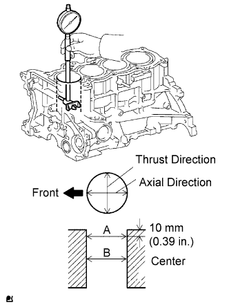 |
Using a cylinder gauge, measure the cylinder bore diameter at positions A and B in the thrust and axial directions.
Calculate the average of the thrust diameter and axial diameter at position A in the illustration.
Calculate the average of thrust diameter and axial diameter at position B in the illustration.
| 3. INSPECT PISTON WITH PIN |
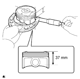 |
Using a micrometer, measure the diameter of the piston. Align the micrometer so it is 37 mm (1.46 in.) from the top of the piston and at a right angle (90°) to the piston pin holes.
 |
Using a caliper gauge, measure the piston pin hole diameter of the piston.
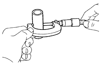 |
Using a micrometer, measure the piston pin diameter.
Subtract the piston pin diameter measurement from the piston pin hole diameter measurement.
| 4. INSPECT PISTON CLEARANCE |
Subtract the piston diameter measurement from the cylinder bore diameter measurement.
| 5. INSPECT CONNECTING ROD |
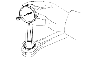 |
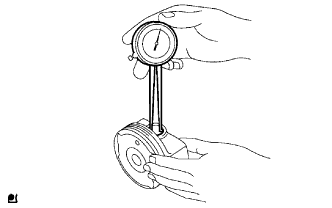
Using a caliper gauge, measure the internal diameter of the connecting rod.
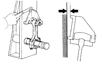 |
Using a rod aligner and feeler gauge, check the connecting rod alignment.
Check for misalignment.
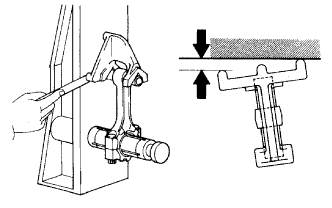 |
Check for twist.
| 6. INSPECT RING GROOVE CLEARANCE |
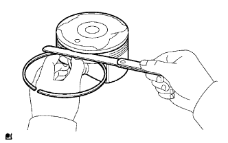 |
Using a feeler gauge, measure the clearance between the new piston ring and the wall of the ring groove.
| Item | Specified Condition |
| No. 1 ring | 0.02 to 0.04 mm (0.0008 to 0.0016 in.) |
| No. 2 ring | 0.02 to 0.06 mm (0.0008 to 0.0024 in.) |
| Oil ring | 0.02 to 0.06 mm (0.0008 to 0.0024 in.) |
| 7. INSPECT PISTON RING END GAP |
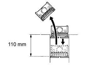 |
Using a piston, push the piston ring a little beyond the bottom of the ring travel, 110 mm (4.33 in.) from the top of the cylinder block.
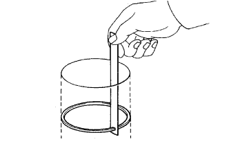 |
Using a feeler gauge, measure the end gap.
| Item | Standard | Maximum |
| No. 1 ring | 0.20 to 0.30 mm (0.0079 to 0.0118 in.) | 0.61 mm (0.0240 in.) |
| No. 2 ring | 0.30 to 0.45 mm (0.0118 to 0.0177 in.) | 1.20 mm (0.0472 in.) |
| Oil ring | 0.10 to 0.40 mm (0.0039 to 0.0158 in.) | 1.15 mm (0.0453 in.) |
| 8. INSPECT CONNECTING ROD BOLT |
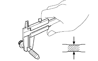 |
Using a vernier caliper, measure the tension portion diameter of the bolt.
| 9. INSPECT CRANKSHAFT |
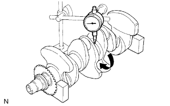 |
Using a dial indicator and V-blocks, measure the circle runout as shown in the illustration.
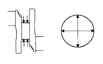 |
Inspect the diameter.
Using a micrometer, measure the diameter of each main journal as illustrated.
Calculate the taper and distortion of the main journal.
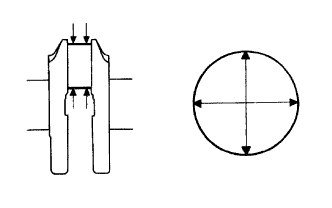 |
Using a micrometer, measure the diameter of each crank pin as illustrated.
Calculate the taper and distortion of the crank pin.
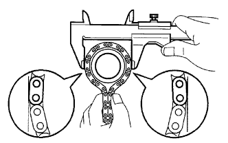 |
Wrap the chain around the timing sprocket as shown in the illustration.
Using a vernier caliper, measure the timing sprocket diameter with the chain wrapped.
| 10. INSPECT CRANKSHAFT BEARING CAP SET BOLT |
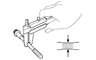 |
Using a vernier caliper, measure the tension portion diameter of the bolt.