 |
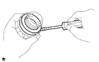
Using a screwdriver, remove the gasket from the oil filler cap.
- HINT:
- Tape the screwdriver tip before use.
ENGINE UNIT > DISASSEMBLY |
| 1. REMOVE SPARK PLUG |
Using a 16 mm plug wrench, remove the 4 spark plugs.
| 2. REMOVE OIL FILLER CAP |
Remove the oil filler cap from the cylinder head cover.
| 3. REMOVE OIL FILLER CAP GASKET |
|
Using a screwdriver, remove the gasket from the oil filler cap.
| 4. REMOVE CAMSHAFT POSITION SENSOR |
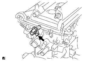 |
Remove the bolt and sensor.
| 5. REMOVE CAMSHAFT TIMING OIL CONTROL VALVE ASSEMBLY |
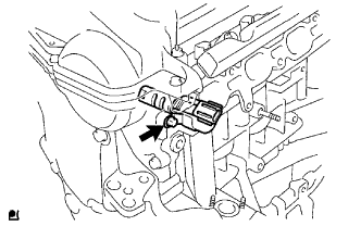 |
Remove the bolt and oil control valve.
| 6. REMOVE OIL FILTER |
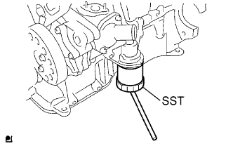 |
Using SST, remove the oil filter.
| 7. REMOVE THERMOSTAT |
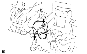 |
Remove the 2 nuts and water inlet.
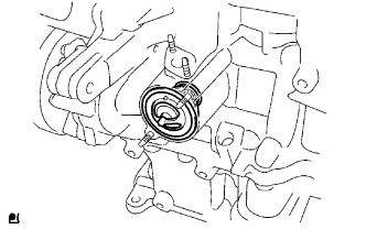 |
Remove the thermostat.
Remove the gasket from the thermostat.
| 8. REMOVE CRANKSHAFT POSITION SENSOR |
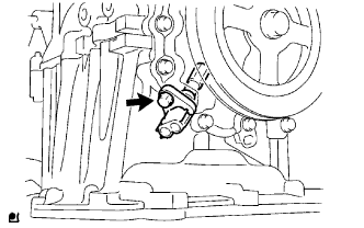 |
Remove the bolt and sensor.
| 9. REMOVE WATER PUMP PULLEY |
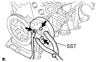 |
Using SST, hold the pump pulley and remove the 3 bolts and pump pulley.
| 10. REMOVE WATER PUMP |
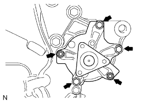 |
Remove the 3 bolts and 2 nuts.
Remove the water pump and gasket.
| 11. REMOVE ENGINE MOUNTING BRACKET RH |
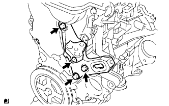 |
Remove the 4 bolts and engine mounting bracket RH.
| 12. REMOVE VENTILATION VALVE |
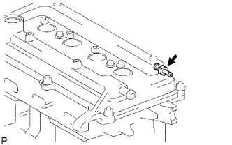 |
Remove the ventilation valve from the cylinder head cover.
| 13. REMOVE CYLINDER HEAD COVER |
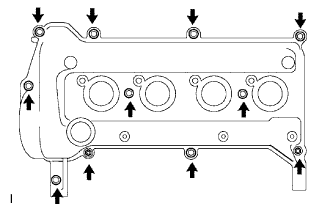 |
Remove the 9 bolts, 2 nuts and cylinder head cover.
Remove the gasket from the cylinder head cover.
| 14. REMOVE CRANKSHAFT PULLEY |
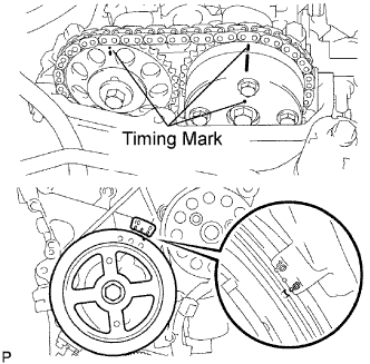 |
Set the No. 1 cylinder to TDC/compression.
Turn the crankshaft pulley until its timing notch and timing mark 0 of the chain cover are aligned.
Check that both timing marks on the camshaft timing sprocket and the camshaft timing gear are facing upward as shown in the illustration.
If not, turn the crankshaft 1 complete revolution (360°) and align the marks as above.
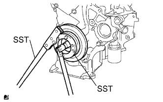 |
Using SST, hold the crankshaft pulley and loosen the crankshaft pulley set bolt.
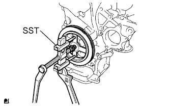 |
Loosen the crankshaft pulley set bolts until 2 to 3 threads of the bolt is tightened to the crankshaft.
Using SST, remove the crankshaft pulley and crankshaft pulley set bolt.
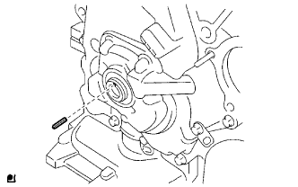 |
Remove the crankshaft straight pin.
| 15. REMOVE TIMING CHAIN COVER |
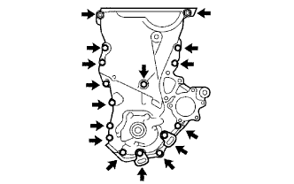 |
Remove the 15 bolts and nut.
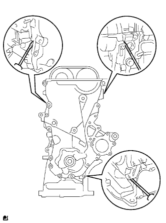 |
Using a screwdriver with the tip wrapped in tape, remove the chain cover by prying between the cylinder head and cylinder block.
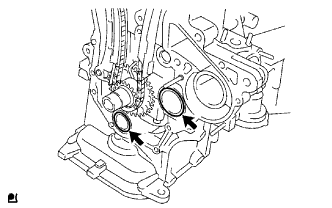 |
Remove the 2 O-rings from the cylinder block and No. 1 oil pan.
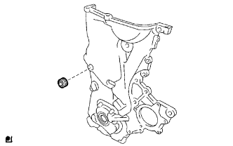 |
Using an 8 mm hexagon wrench, remove the screw plug from the oil pump.
| 16. REMOVE OIL PUMP SEAL |
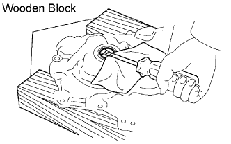 |
If the timing chain cover is removed:
Using a screwdriver, remove the oil seal.
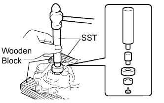 |
Using SST and a hammer, tap in a new oil seal until its surface is flush with the timing chain cover edge.
Apply multi-purpose grease to the lip of the oil seal.
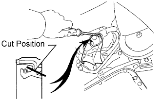 |
If the timing chain cover is installed:
Using a knife, cut off the lip of the oil seal.
Using a screwdriver with the tip wrapped in tape, pry out the oil seal.
Apply multi-purpose grease to the lip of a new oil seal.
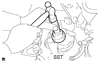 |
Using SST and a hammer, tap in the oil seal until its surface is flush with the timing chain cover edge.
| 17. REMOVE NO. 1 CHAIN TENSIONER |
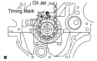 |
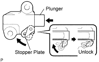 |
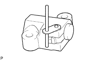
Lift up the stopper plate, then unlock the plunger.
Push in the plunger to the end with the plunger unlocked.
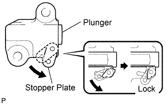 |
Lower the stopper plate with the plunger pushed to the end, then lock the plunger.
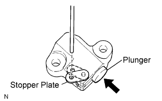 |
Insert a 3.0 mm (0.118 in.) diameter bar into the hole of the stopper plate with the plunger locked.
 |
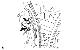 |
Remove the 2 bolts and chain tensioner.
| 18. REMOVE CHAIN TENSIONER SLIPPER |
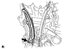 |
Remove the bolt and chain tensioner slipper.
| 19. REMOVE NO. 1 CHAIN VIBRATION DAMPER |
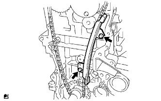 |
Remove the 2 bolts and chain vibration damper.
| 20. REMOVE CHAIN |
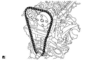 |
Remove the chain from the engine.
| 21. REMOVE FUEL DELIVERY PIPE |
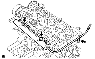 |
Remove the 3 bolts and fuel delivery pipe together with the 4 fuel injectors.
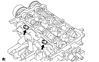 |
Remove the delivery pipe spacer from the cylinder head.
| 22. REMOVE FUEL INJECTOR |
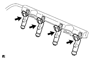 |
Pull out the 4 injectors from the delivery pipe.
| 23. REMOVE NO. 2 CAMSHAFT |
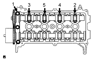 |
Using several steps, uniformly loosen and remove the 11 bearing cap bolts in the sequence shown in the illustration, and then remove the 5 bearing caps and No. 2 camshaft.
| 24. REMOVE CAMSHAFT TIMING SPROCKET |
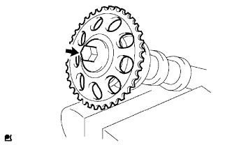 |
Clamp the camshaft in a vise.
Remove the flange bolt and camshaft timing sprocket.
| 25. REMOVE CAMSHAFT |
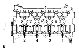 |
Using several steps, uniformly loosen and remove the 8 bearing cap bolts in the sequence shown in the illustration, and then remove the 4 bearing caps and camshaft.
| 26. REMOVE CAMSHAFT TIMING GEAR |
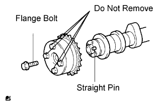 |
Turn the valve timing controller assembly at the most advanced angle .
Remove the flange bolt and camshaft timing gear.
| 27. REMOVE CYLINDER HEAD |
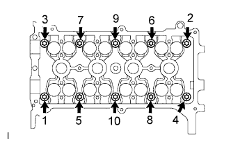 |
Using several steps, uniformly loosen and remove the 10 cylinder head bolts with an 8 mm bi-hexagon wrench in the sequence shown in the illustration. Remove the 10 cylinder head bolts and plate washers.
| 28. REMOVE CYLINDER HEAD GASKET |
| 29. REMOVE OIL FILTER UNION |
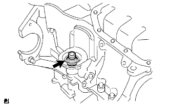 |
Using a 12 mm hexagon wrench, remove the oil filter union.
| 30. REMOVE NO. 2 OIL PAN |
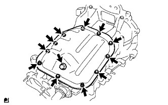 |
Remove the oil pan drain plug and gasket.
Remove the 9 bolts and 2 nuts.
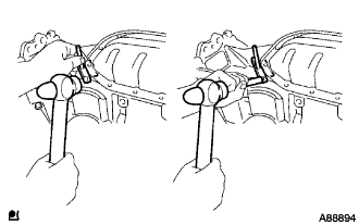 |
Insert the blade of oil pan seal cutter between the oil pan and No. 2 oil pan, cut off the applied sealer and remove the No. 2 oil pan.
| 31. REMOVE OIL STRAINER |
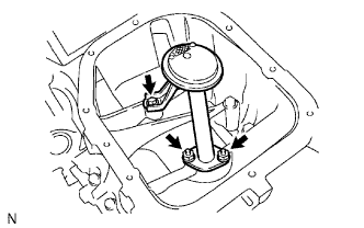 |
Remove the bolt, 2 nuts, oil strainer and gasket.
| 32. REMOVE OIL PAN |
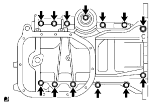 |
Loosen and remove the 13 bolts uniformly in several steps.
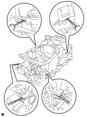 |
Using a screwdriver, remove the oil pan by prying between the cylinder block and oil pan.
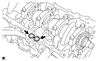 |
Remove the 2 O-rings from the cylinder block.
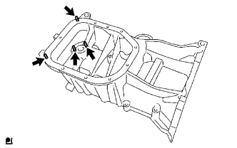 |
Using an E5 "TORX" socket, remove the 4 stud bolts.
| 33. REMOVE ENGINE REAR OIL SEAL |
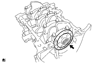 |
| 34. INSPECT CONNECTING ROD THRUST CLEARANCE |
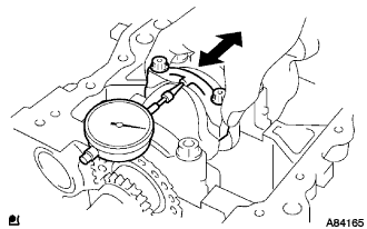 |
Using a dial indicator, measure the thrust clearance while moving the connecting rod back and forth.
| 35. INSPECT CONNECTING ROD OIL CLEARANCE |
Check that the matchmarks on the connecting rod and cap are aligned to ensure the correct reassembly.
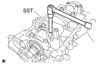 |
Using SST, remove the 2 connecting rod cap bolts.
Using the 2 removed connecting rod cap bolts, remove the connecting rod cap and lower bearing by wiggling the connecting rod cap right and left.
Clean the crank pin and bearing.
Check the crank pin and bearing for pitting and scratches.
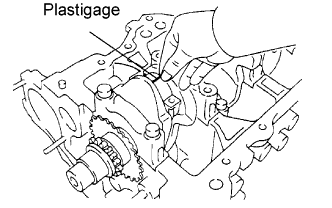 |
Lay a strip of Plastigage across the crank pin.
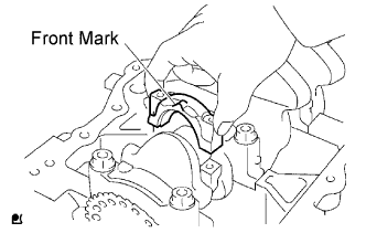 |
Match together the connecting rod and cap in the correct combination. Then install the cap onto the connecting rod, making sure that the front mark on the cap is correctly oriented.
Apply a light coat of engine oil to the threads of the connecting rod cap bolts.
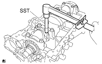 |
Using SST, tighten the bolts in several steps by the specified torque.
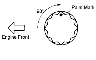 |
Mark the front of the connecting cap bolts with paint.
Retighten the cap bolts by 90° as shown in the illustration.
Remove the 2 bolts, connecting rod cap and lower bearing.
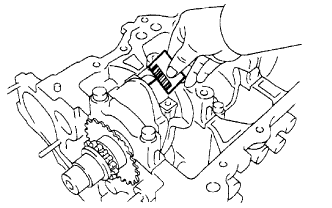 |
Measure the Plastigage at its widest point.
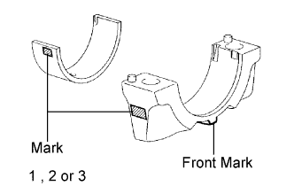 |
If the oil clearance is greater than the maximum, select and replace the bearing. If necessary, use an undersized bearing.
| Number Mark | Connecting Rod External Diameter | Center Bearing Thickness | Oil Clearance |
| 1 | 43.000 to 43.008 mm (1.6929 to 1.6932 in.) | 1.491 to 1.492 mm (0.0587 to 0.0588 in.) | 0.016 to 0.040 mm (0.0006 to 0.0016 in.) |
| 2 | 43.008 to 43.016 mm (1.6932 to 1.6935 in.) | 1.492 to 1.496 mm (0.0588 to 0.0589 in.) | 0.016 to 0.040 mm (0.0006 to 0.0016 in.) |
| 3 | 43.016 to 43.024 mm (1.6935 to 1.6939 in.) | 1.496 to 1.500 mm (0.0589 to 0.0591 in.) | 0.016 to 0.040 mm (0.0006 to 0.0016 in.) |
| U/S 0.25 | 43.000 to 43.024 mm (1.6929 to 1.6939 in.) | 1.608 to 1.614 mm (0.0633 to 0.0635 in.) | 0.016 to 0.040 mm (0.0006 to 0.0016 in.) |
| 36. REMOVE PISTON WITH CONNECTING ROD |
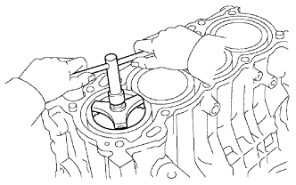 |
Using a ridge reamer, remove all carbon from the top of the cylinder.
Push the piston, connecting rod assembly and upper bearing through the top of the cylinder block.
| 37. REMOVE CONNECTING ROD BEARING |
| 38. INSPECT CRANKSHAFT THRUST CLEARANCE |
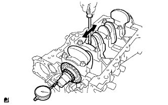 |
Using a dial indicator, measure the thrust clearance while prying the crankshaft back and forth with a screwdriver.
| 39. REMOVE CRANKSHAFT AND INSPECT OIL CLEARANCE |
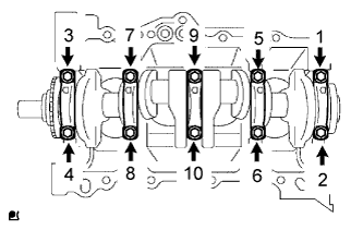 |
Using several steps, uniformly loosen and remove the 10 bearing cap bolts with SST in the sequence shown in the illustration.
Remove the 5 bearing caps and crankshaft.
Clean each main journal and bearing.
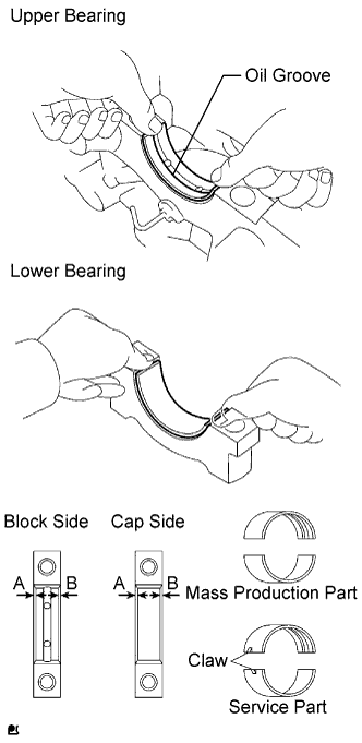 |
Install the upper bearing with the oil groove onto the cylinder block, and the lower bearing onto the bearing cap.
Install the crankshaft onto the cylinder block.
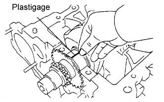 |
Lay a strip of Plastigage across each journal.
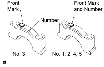 |
Check the front marks and numbers and install the bearing caps onto the cylinder block.
Apply a light coat of engine oil to the threads of the bearing cap bolts.
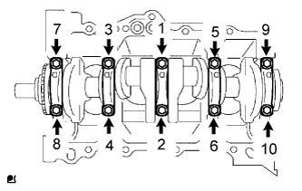 |
Using SST, tighten the bolts in several steps by the specified torque in the sequence shown in the illustration.
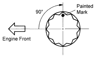 |
Mark the front of the bearing cap bolts with paint.
Retighten the bearing cap bolts by 90° in the same sequence.
Check that the painted mark is now at a 90° angle to the front.
Remove the bearing cap.
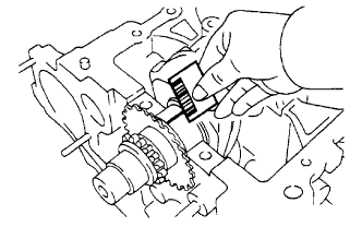 |
Measure the Plastigage at its widest point.
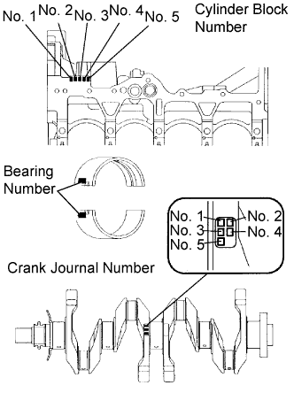 |
| Number | Specified Condition |
| 0 | 50.000 to 50.003 mm (1.9685 to 1.9686 in.) |
| 1 | 50.003 to 50.005 mm (1.9686 to 1.9687 in.) |
| 2 | 50.005 to 50.007 mm (1.9687 to 1.9688 in.) |
| 3 | 50.007 to 50.010 mm (1.9688 to 1.9689 in.) |
| 4 | 50.010 to 50.012 mm (1.9689 to 1.9690 in.) |
| 5 | 50.012 to 50.014 mm (1.9690 to 1.9691 in.) |
| 6 | 50.014 to 50.016 mm (1.96905 to 1.96913 in.) |
| Number | Specified Condition |
| 0 | 45.998 to 46.000 mm (1.8109 to 1.8110 in.) |
| 1 | 45.996 to 45.998 mm (1.81086 to 1.81094 in.) |
| 2 | 45.994 to 45.996 mm (1.8108 to 1.8109 in.) |
| 3 | 45.992 to 45.994 mm (1.81071 to 1.81079 in.) |
| 4 | 45.990 to 45.992 mm (1.8106 to 1.8107 in.) |
| 5 | 45.988 to 45.990 mm (1.81055 to 1.81063 in.) |
| Cylinder Block Number + Crank Journal Number | Bearing Number | Center Bearing Thickness | Oil Clearance |
| 0 to 2 | 1 | 1.992 to 1.995 mm (0.0784 to 0.0785 in.) | 0.010 to 0.023 mm (0.0004 to 0.0009 in.) |
| 3 to 5 | 2 | 1.995 to 1.998 mm (0.0785 to 0.0787 in.) | Same as above |
| 6 to 8 | 3 | 1.998 to 2.001 mm (0.0787 to 0.0788 in.) | Same as above |
| 9 to 11 | 4 | 2.001 to 2.004 mm (0.0788 to 0.0789 in.) | Same as above |
| - | U/S 0.25 | 2.111 to 2.117 mm (0.0831 to 0.0834 in.) | Same as above |
| 40. REMOVE CRANKSHAFT BEARING |
| 41. REMOVE CRANKSHAFT THRUST WASHER |
| 42. REMOVE PISTON RING SET |
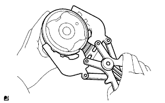 |
Using a piston ring expander, remove the 2 compression rings.
Remove the oil ring (side rail and expander) by hand.
| 43. REMOVE PISTON PIN |
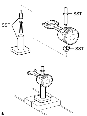 |
Using SST, press out the piston pin from the piston.
| 44. REMOVE CYLINDER BLOCK WATER DRAIN COCK |
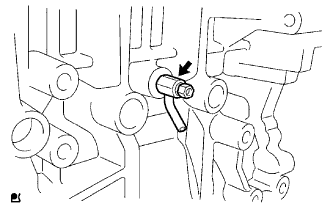 |
Remove the cylinder block water drain cock from the cylinder block.
| 45. REMOVE OIL JET |
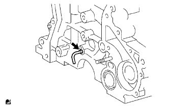 |
Remove the oil jet from the cylinder block.
| 46. REMOVE STUD BOLT |
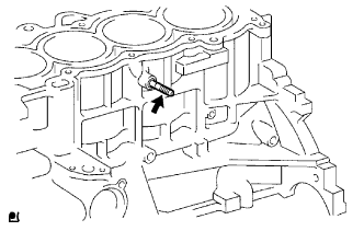 |
Remove the stud bolt for the knock control sensor from the cylinder block.
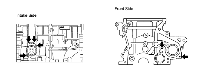
Using an E5 "TORX" socket, remove the 6 stud bolts from the cylinder block.
| 47. REMOVE RING PIN |
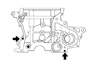 |
Remove the 2 oil pump ring pins from the cylinder block.
| 48. REMOVE STRAIGHT PIN |
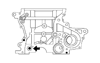 |
Remove the chain tensioner straight pin from the cylinder block.
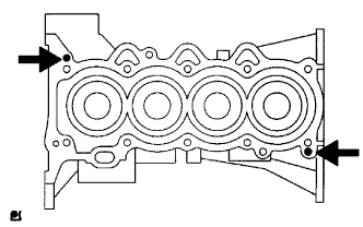 |
Remove the 2 cylinder head straight pins from the cylinder block.
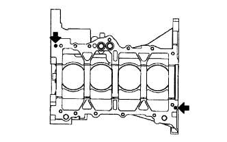 |
Remove the 2 oil pan straight pins from the cylinder block.
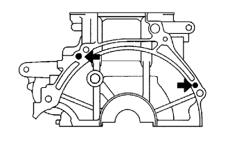 |
Remove the 2 end plate straight pins from the cylinder block.
| 49. REMOVE TIGHT PLUG |