 |
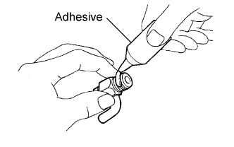
Apply adhesive to 2 or 3 threads of the drain cock, and install it within 3 minutes.
- Adhesive:
- Toyota Genuine Adhesive 1344, Three Bond 1344 or equivalent
ENGINE UNIT > REASSEMBLY |
| 1. INSTALL CYLINDER BLOCK WATER DRAIN COCK |
|
Apply adhesive to 2 or 3 threads of the drain cock, and install it within 3 minutes.
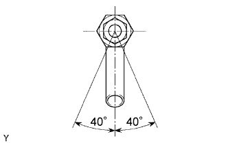 |
Tighten the drain cock to the specified torque. Then rotate the drain cock clockwise until its drain port faces downward.
| 2. INSTALL TIGHT PLUG |
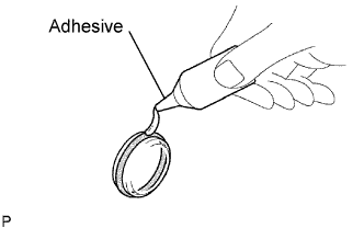 |
Apply adhesive to new tight plugs.
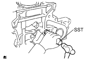 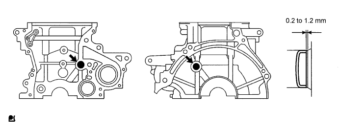 |
Using SST, tap in the tight plugs as shown in the illustration.
| 3. INSTALL STRAIGHT PIN |
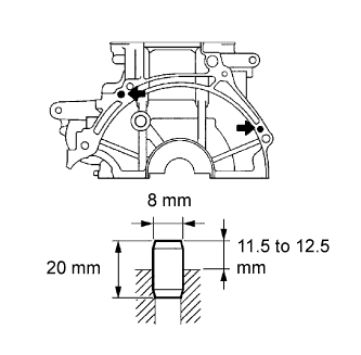 |
Using a plastic-faced hammer, tap in a new end plate straight pin.
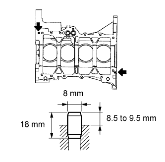 |
Using a plastic-faced hammer, tap in a new oil pan straight pin.
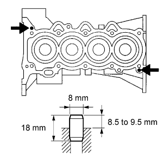 |
Using a plastic-faced hemmer, tap in a new cylinder head straight pin.
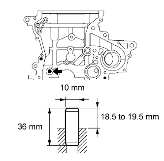 |
Using a plastic-faced hammer, tap in a new chain tensioner straight pin.
| 4. INSTALL RING PIN |
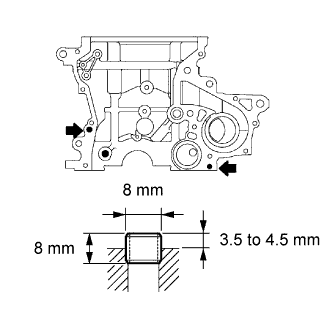 |
Using a plastic-faced hammer, tap in a new oil pump ring pin.
| 5. INSTALL STUD BOLT |
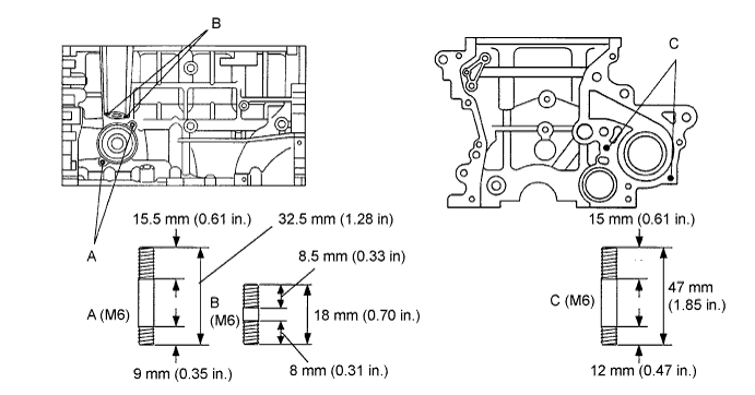
Using an E5 "TORX" socket, install the 6 stud bolts.
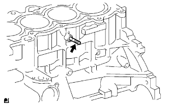 |
Install the stud bolt for the knock sensor to the cylinder block.
| 6. INSTALL OIL JET |
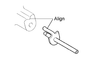 |
Align the concave of the cylinder block with the bracket of the oil jet, then tap in the oil jet (the service part).
| 7. INSTALL CRANKSHAFT |
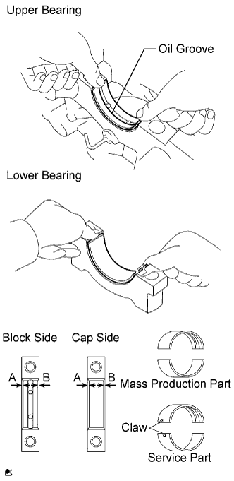 |
Install the upper bearing with the oil groove onto the cylinder block, and the lower bearing onto the bearing cap.
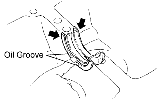 |
Install the 2 thrust washers onto the No. 3 journal position of the cylinder block with the oil grooves facing outward.
Apply engine oil to the upper bearing and install the crankshaft onto the cylinder block.
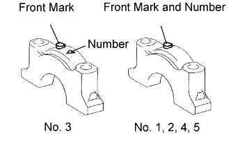 |
Check the front marks and numbers and install the bearing caps onto the cylinder block.
Apply a light coat of engine oil to the threads of the bearing cap bolts.
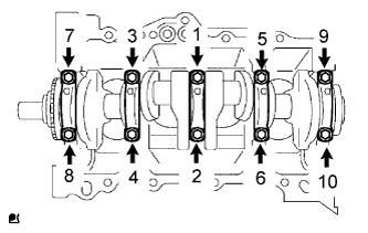 |
Using SST, tighten the bolts in several steps by the specified torque in the sequence shown in the illustration.
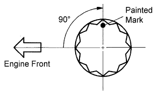 |
Mark the front of the bearing cap bolts with paint.
Retighten the bearing cap bolts by 90° in the same sequence.
Check that the painted mark is now at a 90° angle to the front.
| 8. INSTALL PISTON PIN |
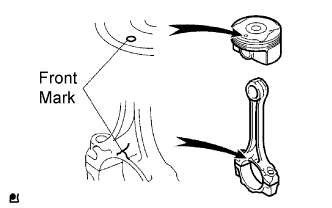 |
Apply engine oil to the piston pin and the inside surface of the connecting rod.
Align the front marks of the piston and connecting rod.
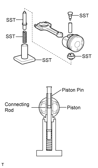 |
Using SST, push in the piston pin.
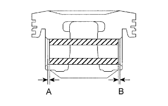 |
Check the piston pin position.
| 9. INSTALL CONNECTING ROD BEARING |
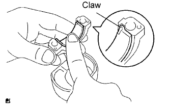 |
Align the bearing claw with the grooves of the connecting rod and connecting rod cap.
| 10. INSTALL PISTON RING SET |
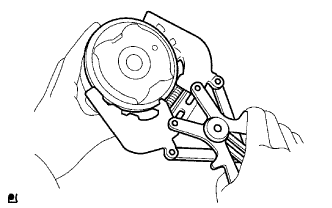 |
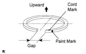 |
Install the 2 compression rings and oil ring.
| Part | Paint Color | Code Mark |
| No. 1 compression ring | Red | 1R |
| No. 2 compression ring | Blue | 2R |
| Oil ring | - | - |
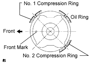 |
Position the piston rings so that the ring ends are as shown in the illustration.
| 11. INSTALL PISTON WITH CONNECTING ROD |
Apply engine oil to the cylinder walls, pistons, and the surfaces of the connecting rod bearings.
Check the position of the piston ring ends.
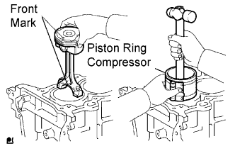 |
Using a piston ring compressor, push the correctly numbered piston and connecting rod assemblies into each cylinder with the front mark on the piston facing forward.
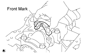 |
Match the connecting rod and cap together in the correct combination. Then install the cap onto the connecting rod, making sure that the front mark on the cap is correctly oriented.
Apply a light coat of engine oil to the threads of the connecting rod cap bolts.
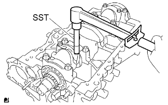 |
Using SST, tighten the bolts in several steps by the specified torque.
|
Mark the front of the connecting cap bolts with paint.
Retighten the cap bolts by 90° as shown.
Check that the crankshaft turns smoothly.
| 12. INSTALL OIL PAN |
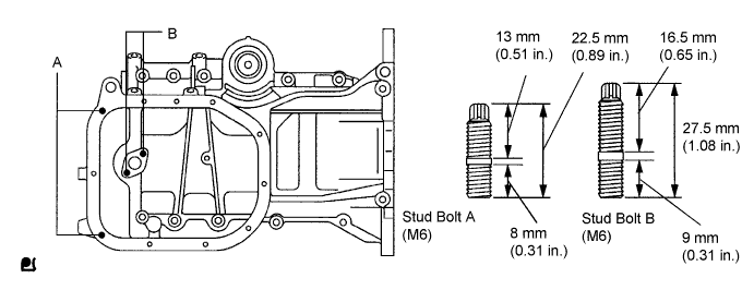
Using an E5 "TORX" socket, install the 4 stud bolts.
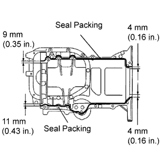 |
Apply a continuous line of seal packing to the oil pan mating surface as shown in the illustration.
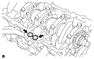 |
Install 2 new O-rings onto the cylinder block.
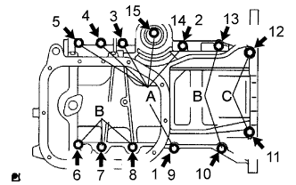 |
Using several steps, install and uniformly tighten the 13 bolts in the sequence shown in the illustration.
| 13. INSTALL ENGINE REAR OIL SEAL |
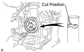 |
Using a knife, cut off the lip of the oil seal.
Using a screwdriver with the tip wrapped in tape, pry out the oil seal.
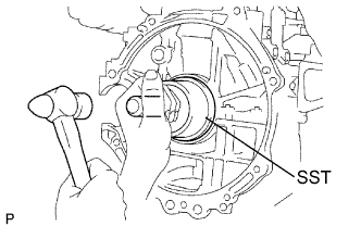 |
Apply multi-purpose grease to the lip of a new oil seal.
Using SST and a hammer, tap in the oil seal until its surface is flush with the rear oil seal retainer edge.
| 14. INSTALL OIL STRAINER |
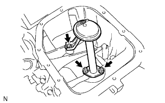 |
Install a new gasket and the oil strainer with the 2 nuts and bolt.
| 15. INSTALL NO. 2 OIL PAN |
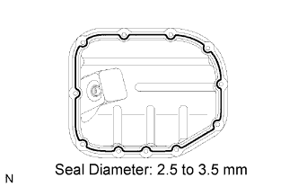 |
Apply a continuous line of seal packing to the oil pan mating surface as shown in the illustration.
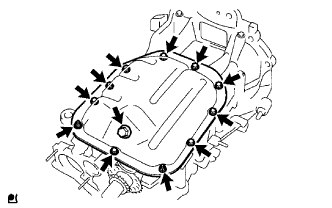 |
Install the No. 2 oil pan with the 9 bolts and 2 nuts.
Install the drain plug with a new gasket.
| 16. INSTALL OIL FILTER UNION |
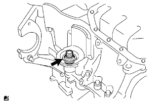 |
Using a 12 mm hexagon wrench, install the oil filter union.
| 17. INSTALL OIL FILTER |
Check and clean the oil filter installation surface.
Apply clean engine oil to the gasket of a new oil filter.
Lightly screw the oil filter into place, and tighten it until the gasket comes into contact with the seat.
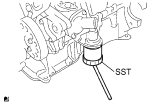 |
Using SST, tighten it an additional 3/4 turn.
| 18. INSTALL CYLINDER HEAD GASKET |
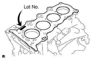 |
Place a new cylinder head gasket on the cylinder block with the Lot No. stamp facing upward.
| 19. INSTALL CYLINDER HEAD |
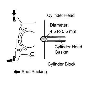 |
Apply seal packing as shown in the illustration.
Apply a light coat of engine oil to the threads of the cylinder head bolts.
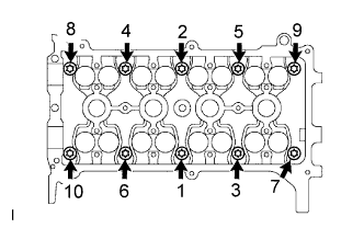 |
Using several steps, install and uniformly tighten the 10 cylinder head bolts and plate washers with an 8 mm bi-hexagon wrench in the sequence shown in the illustration.
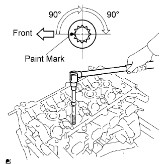 |
Mark the front of the cylinder head bolt with paint.
Retighten the cylinder head bolts by an additional 90° and then another 90°, as shown in the illustration.
Check that the painted mark is now at a 180° angle to the front.
| 20. INSTALL CAMSHAFT TIMING GEAR |
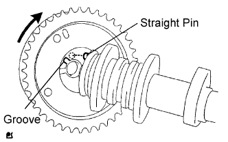 |
Put the camshaft timing gear and camshaft together so that the straight pin and key groove are offset, as shown in the illustration.
Turn the camshaft timing gear assembly clockwise while pushing it lightly towards the camshaft. Push further at the position where the pin fits into the groove.
Check that there is no clearance between the gear fringe and the camshaft.
Tighten the flange bolt with the camshaft timing gear fixed in place.
Check that the camshaft timing gear can move to the retard angle (to the right) and is locked in the most retarded position.
| 21. INSTALL CAMSHAFT |
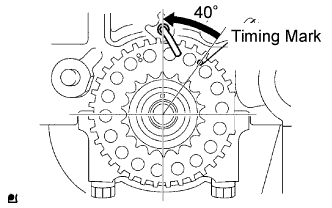 |
Turn the crankshaft by 40° counterclockwise from TDC/compression.
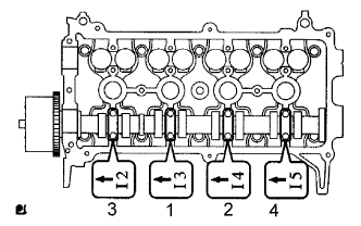 |
Apply a light coat of engine oil to the camshaft journals.
Place the camshaft on the cylinder head with the timing mark on the camshaft timing gear facing upward.
Examine the front marks and numbers, and tighten the bolts in the sequence shown in the illustration.
| 22. INSTALL CAMSHAFT TIMING SPROCKET |
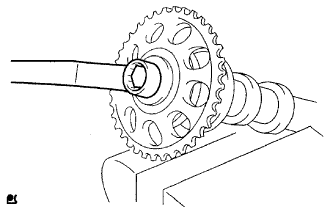 |
Clamp the camshaft in a vise.
Align the knock pin hole of the camshaft timing sprocket with the knock pin of the camshaft, and install the camshaft timing sprocket.
| 23. INSTALL NO. 2 CAMSHAFT |
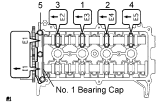 |
Apply a light coat of engine oil to the camshaft journals.
Place the camshaft on the cylinder head with the timing mark on the camshaft timing gear facing upward.
Examine the front marks and numbers, and tighten the bolts in the sequence shown in the illustration.
Install the No. 1 bearing cap.
| 24. INSTALL CHAIN |
Set the position of the No. 1 cylinder to 20° ATDC.
|
Set the crankshaft between 40 to 140° ATDC.
Set the cams of the intake and exhaust timing sprockets to 20° ATDC.
Reset the crankshaft to 20° ATDC.
Install the chain vibration damper with the 2 bolts.
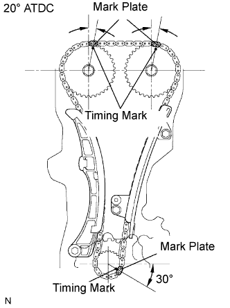 |
Align the timing marks of the camshaft timing sprocket, camshaft timing gear and crankshaft timing sprocket with each mark plate (colored in yellow) of the timing chain.
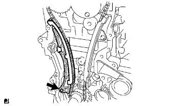 |
Install the chain tensioner slipper with the bolt.
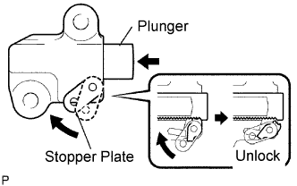 |
Install the chain tensioner with the 2 bolts.
Lift up the stopper plate, then unlock the plunger.
Push in the plunger to the end with the plunger unlocked.
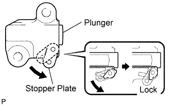 |
Lower the stopper plate with the plunger pushed to the end, then lock the plunger.
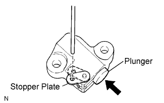 |
Insert a 3.0 mm (0.118 in.) diameter bar into the hole of the stopper plate with the plunger locked.
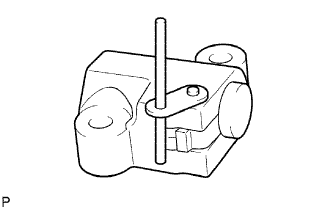 |
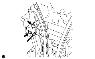 |
Install the chain tensioner with the 2 bolts.
Remove the bar from the chain tensioner.
Check the tension between the intake and exhaust camshaft timing sprockets.
| 25. INSTALL OIL PUMP SEAL |
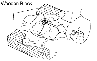 |
If the timing chain cover is removed:
Using a screwdriver, remove the oil seal.
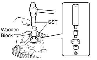 |
Using SST and a hammer, tap in a new oil seal until its surface is flush with the timing chain cover edge.
Apply multi-purpose grease to the lip of the oil seal.
 |
If the timing chain cover is installed:
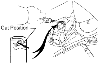
Using a knife, cut off the lip of the oil seal.
Using a screwdriver with the tip wrapped in tape, pry out the oil seal.
Apply multi-purpose grease to the lip of a new oil seal.
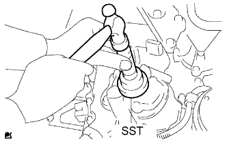 |
Using SST and a hammer, tap in the oil seal until its surface is flush with the timing chain cover edge.
| 26. INSTALL TIMING CHAIN COVER |
 |
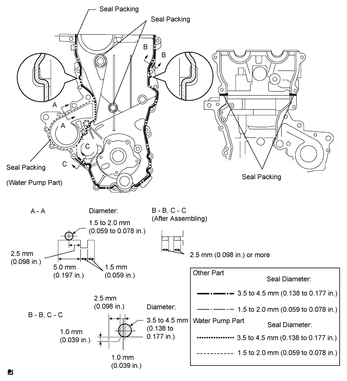
Remove any old packing material from the contact surface.
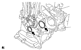
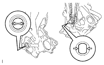
Install 2 new O-rings onto the 2 locations as shown in the illustration.
Apply seal packing to the oil pump assembly, cylinder head and cylinder block as shown in the illustration below.
 |
Align the keyway of the oil pump drive rotor with the rectangular portion of the crankshaft, and slide the oil pump into place.
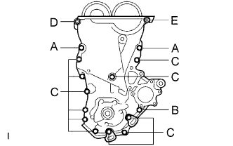 |
Install the oil pump assembly with the 15 bolts and nut. Uniformly tighten the bolts and nut in several steps.
| 27. INSTALL CRANKSHAFT PULLEY |
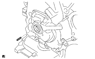 |
Install the crankshaft straight pin to the crankshaft.
Align the hole of the crankshaft pulley with the straight pin, then install the crankshaft pulley.
Using SST, hold the crankshaft pulley and tighten the crankshaft bolt.
| 28. INSTALL WATER PUMP |
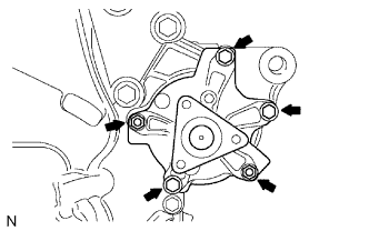 |
Install a new gasket and the water pump with the 3 bolts and 2 nuts.
| 29. INSTALL ENGINE MOUNTING BRACKET RH |
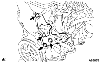 |
Install the engine mounting bracket RH with the 4 bolts.
| 30. INSPECT VALVE CLEARANCE |
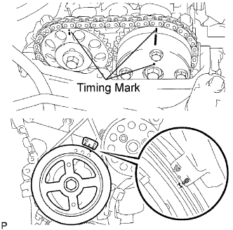 |
Set the No. 1 cylinder to TDC/compression.
Turn the crankshaft pulley until its timing notch and timing mark 0 of the chain cover are aligned.
Check that both timing marks on the camshaft timing sprocket and camshaft timing gear are facing upward as shown in the illustration.
If not, turn the crankshaft 1 complete revolution (360°) and align the marks as above.
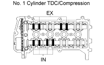 |
Check the valves indicated in the illustration.
Using a feeler gauge, measure the clearance between the valve lifter and camshaft.
| Item | Specified Condition |
| Intake | 0.17 to 0.23 mm (0.007 to 0.009 in.) |
| Exhaust | 0.27 to 0.33 mm (0.011 to 0.013 in.) |
Record any out-of-specification valve clearance measurements. They will be used later to determine the required replacement adjusting shim.
Turn the crankshaft 1 complete revolution until its timing notch and timing mark 0 of the chain cover are aligned.
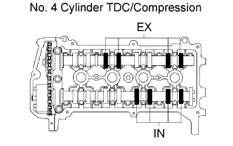 |
Check the valves indicated in the illustration.
Using a feeler gauge, measure the clearance between the valve lifter and camshaft.
| Item | Specified Condition |
| Intake | 0.17 to 0.23 mm (0.007 to 0.009 in.) |
| Exhaust | 0.27 to 0.33 mm (0.011 to 0.013 in.) |
Record any out-of-specification valve clearance measurements. They will be used later to determine the required replacement adjusting shim.
| 31. ADJUST VALVE CLEARANCE |
|
Set the No. 1 cylinder to TDC/compression.
Turn the crankshaft pulley until its timing notch and timing mark 0 of the chain cover are aligned.
Check that both timing marks on the camshaft timing sprocket and valve timing controller assembly are facing upward as shown in the illustration.
If not, turn the crankshaft 1 complete revolution (360°) and align the marks as above.
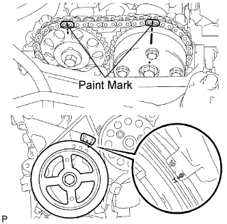 |
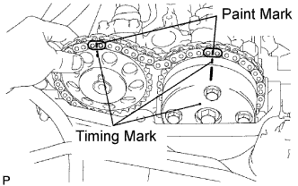
Put paint marks on the timing chain where the timing marks of the camshaft timing sprocket and the camshaft timing gear are located.
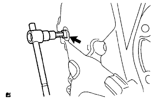 |
Using an 8 mm hexagon wrench, remove the screw plug.
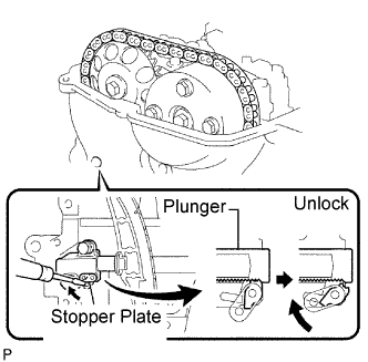 |
Insert a screwdriver into the service hole of the chain tensioner to hold the stopper plate of the chain tensioner at an upward position.
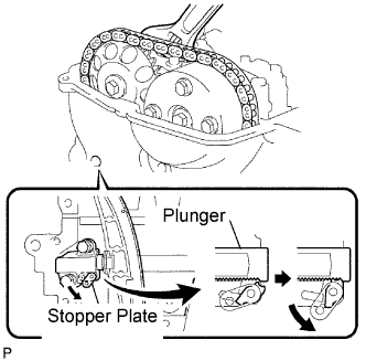 |
Keeping the stopper plate of the chain tensioner lifted, slightly rotate the hexagonal lobe of the No. 2 camshaft to the right with an adjustable wrench so the plunger of the chain tensioner is pushed.
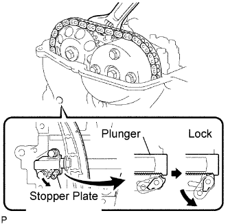 |
Keeping the adjustable wrench installed, remove the screwdriver with the plunger pushed.
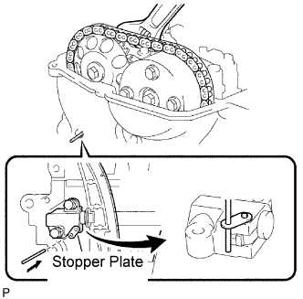 |
Insert a 3.0 mm (0.118 in.) diameter bar into the hole of the stopper plate with the stopper plate of the chain tensioner lowered and locked.
Secure the 3.0 mm (0.118 in.) diameter bar with tape.
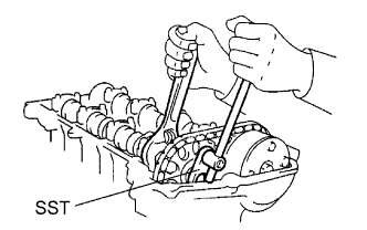 |
Hold the hexagonal lobe of the camshaft No. 2 with the adjustable wrench.
Using SST, loosen the bolt.
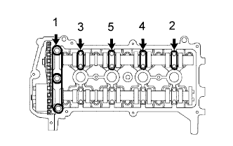 |
Using several steps, uniformly loosen and remove the 11 bearing cap bolts in the sequence shown in the illustration. Then remove the 5 bearing caps.
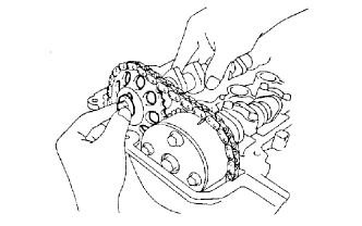 |
Remove the flange bolt with the No. 2 camshaft lifted up. Then detach the No. 2 camshaft and the camshaft timing sprocket.
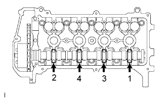 |
Using several steps, uniformly loosen and remove the 8 bearing cap bolts in the sequence shown in the illustration. Then remove the 4 bearing caps.
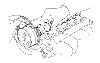 |
Hold the timing chain with one hand, and remove the camshaft and the camshaft timing gear assembly.
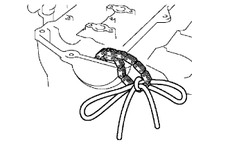 |
Tie the timing chain with a string as shown in the illustration.
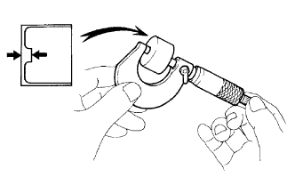 |
Remove the valve lifters.
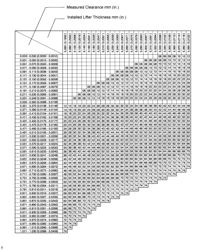
Using a micrometer, measure the thickness of the removed lifter.
Calculate the thickness of a new lifter so that the valve clearance comes within the specified value.
| A | New lifter thickness |
| B | Used lifter thickness |
| C | Measured valve clearance |
| Item | Thickness |
| Intake | A = B + (C - 0.20 mm (0.008 in.)) |
| Exhaust | A = B + (C - 0.30 mm (0.012 in.)) |
Select a new lifter with the thickness as close to the calculated values as possible.
EXAMPLE: (Intake)
Measured valve clearance = 0.40 mm (0.0158 in.)
0.40 mm (0.0158 in.) - 0.20 mm (0.0079 in.) = 0.20 mm (0.0079 in.)
(Measured - Specification = Excess clearance)
Used lifter measurement = 5.25 mm (0.2067 in.)
0.20 mm (0.0079 in.) + 5.25 mm (0.2067 in.) = 5.45 mm (0.2146 in.)
(Excess clearance + Used lifter = Ideal new lifter)
Closest new lifter = 5.45 mm (0.2146 in.)
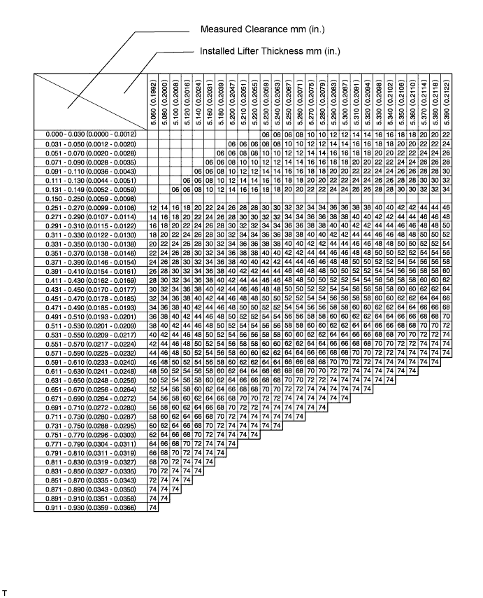
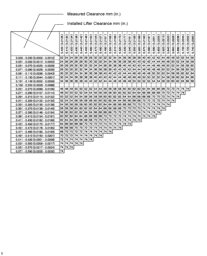
Select No. 46 lifter (5.46 mm (0.2150 in.))
Valve lifter selection chart (intake)
Valve lifter selection chart (intake) (continued).
| Lifter No. | Thickness | Lifter No. | Thickness | Lifter No. | Thickness |
| 06 | 5.060 mm (0.1992 in.) | 30 | 5.300 mm (0.2087 in.) | 54 | 5.540 mm (0.2181 in.) |
| 08 | 5.080 mm (0.2000 in.) | 32 | 5.320 mm (0.2094 in.) | 56 | 5.560 mm (0.2189 in.) |
| 10 | 5.100 mm (0.2008 in.) | 34 | 5.340 mm (0.2102 in.) | 58 | 5.580 mm (0.2197 in.) |
| 12 | 5.120 mm (0.2016 in.) | 36 | 5.360 mm (0.2110 in.) | 60 | 5.600 mm (0.2205 in.) |
| 14 | 5.140 mm (0.2024 in.) | 38 | 5.380 mm (0.2118 in.) | 62 | 5.620 mm (0.2213 in.) |
| 16 | 5.160 mm (0.2031 in.) | 40 | 5.400 mm (0.2126 in.) | 64 | 5.640 mm (0.2220 in.) |
| 18 | 5.180 mm (0.2039 in.) | 42 | 5.420 mm (0.2134 in.) | 66 | 5.660 mm (0.2228 in.) |
| 20 | 5.200 mm (0.2047 in.) | 44 | 5.440 mm (0.2142 in.) | 68 | 5.680 mm (0.2236 in.) |
| 22 | 5.220 mm (0.2055 in.) | 46 | 5.460 mm (0.2150 in.) | 70 | 5.700 mm (0.2244 in.) |
| 24 | 5.240 mm (0.2063 in.) | 48 | 5.480 mm (0.2157 in.) | 72 | 5.720 mm (0.2252 in.) |
| 26 | 5.260 mm (0.2071 in.) | 50 | 5.500 mm (0.2165 in.) | 74 | 5.740 mm (0.2260 in.) |
| 28 | 5.280 mm (0.2079 in.) | 52 | 5.520 mm (0.2173 in.) | - | - |
Valve lifter selection chart (exhaust).
Valve selection chart (exhaust) (continued).
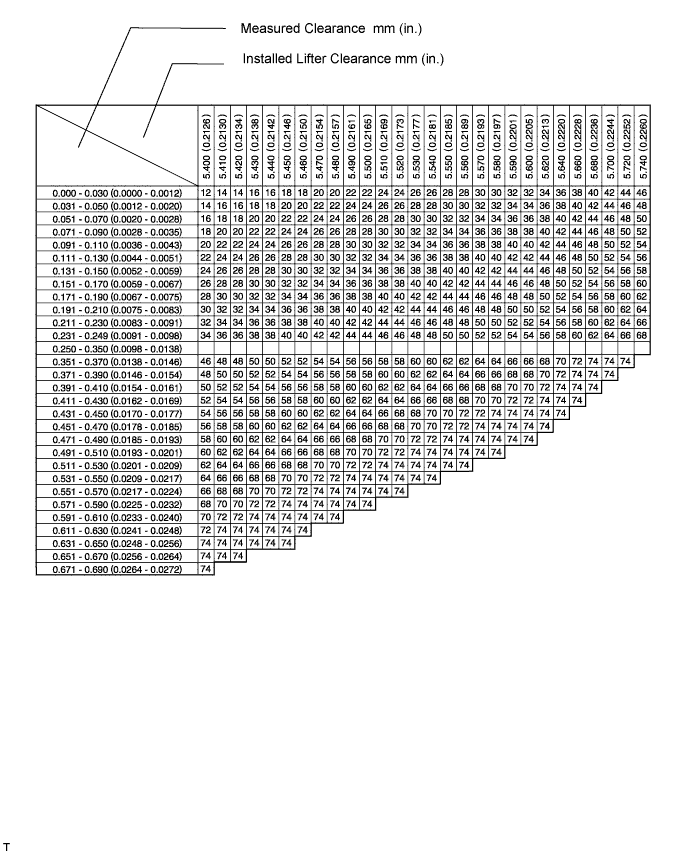
| Lifter No. | Thickness | Lifter No. | Thickness | Lifter No. | Thickness |
| 06 | 5.060 mm (0.1992 in.) | 30 | 5.300 mm (0.2087 in.) | 54 | 5.540 mm (0.2181 in.) |
| 08 | 5.080 mm (0.2000 in.) | 32 | 5.320 mm (0.2094 in.) | 56 | 5.560 mm (0.2189 in.) |
| 10 | 5.100 mm (0.2008 in.) | 34 | 5.340 mm (0.2102 in.) | 58 | 5.580 mm (0.2197 in.) |
| 12 | 5.120 mm (0.2016 in.) | 36 | 5.360 mm (0.2110 in.) | 60 | 5.600 mm (0.2205 in.) |
| 14 | 5.140 mm (0.2024 in.) | 38 | 5.380 mm (0.2118 in.) | 62 | 5.620 mm (0.2213 in.) |
| 16 | 5.160 mm (0.2031 in.) | 40 | 5.400 mm (0.2126 in.) | 64 | 5.640 mm (0.2220 in.) |
| 18 | 5.180 mm (0.2039 in.) | 42 | 5.420 mm (0.2134 in.) | 66 | 5.660 mm (0.2228 in.) |
| 20 | 5.200 mm (0.2047 in.) | 44 | 5.440 mm (0.2142 in.) | 68 | 5.680 mm (0.2236 in.) |
| 22 | 5.220 mm (0.2055 in.) | 46 | 5.460 mm (0.2150 in.) | 70 | 5.700 mm (0.2244 in.) |
| 24 | 5.240 mm (0.2063 in.) | 48 | 5.480 mm (0.2157 in.) | 72 | 5.720 mm (0.2252 in.) |
| 26 | 5.260 mm (0.2071 in.) | 50 | 5.500 mm (0.2165 in.) | 74 | 5.740 mm (0.2260 in.) |
| 28 | 5.280 mm (0.2079 in.) | 52 | 5.520 mm (0.2173 in.) | - | - |
Reinstall the selected valve lifters.
Apply a light coat of engine oil to the camshaft journals.
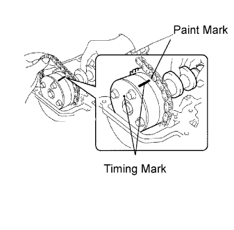 |
Install the timing chain onto the camshaft timing gear with the paint mark and the timing mark aligned as shown in the illustration.
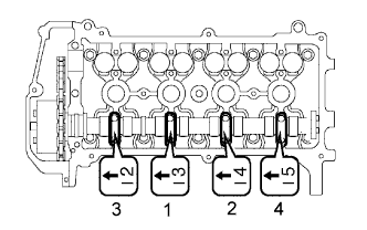 |
Examine the front marks and numbers, and tighten the bolts in the sequence shown in the illustration.
 |
Hold the timing chain, and align the timing mark on the camshaft timing sprocket with the paint mark of the timing chain.
|
Align the alignment pin hole on the camshaft timing sprocket with the alignment pin of the camshaft, and install the sprocket into the camshaft.
Temporarily install the timing sprocket bolt.
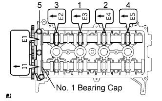 |
Examine the front marks and numbers, and tighten the bolts in the sequence shown in the illustration.
Install the No. 1 bearing cap.
|
Hold the hexagonal lobe of the No. 2 camshaft with the adjustable wrench.
Using SST, tighten the bolt.
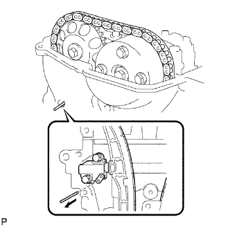 |
Remove the bar from the timing chain tensioner.
|
Turn the crankshaft pulley until its timing notch and timing mark 0 of the chain cover are aligned.
Check that all the pairs of the timing marks are aligned.
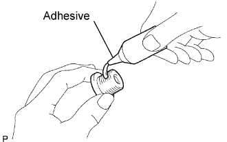 |
Apply seal packing to 2 or 3 threads of the screw plug end.
|
Using an 8 mm hexagon wrench, install the screw plug.
| 32. INSTALL FUEL INJECTOR |
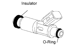 |
Install new insulators onto each fuel injector.
Apply a light coat of spindle oil or gasoline to new O-rings and install them onto each fuel injector.
Apply a light coat of spindle oil or gasoline to the place where a delivery pipe comes into contact with the O-ring.
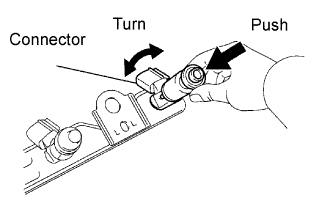 |
While turning the injector clockwise and counterclockwise, install it to the delivery pipe.
| 33. INSTALL FUEL DELIVERY PIPE |
Install the 2 spacers onto the cylinder head.
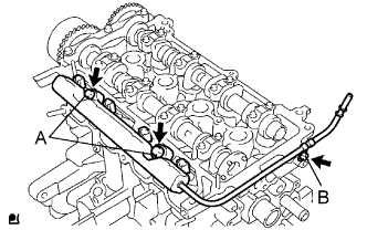 |
Install the fuel delivery pipe and 4 fuel injectors together.
| 34. INSTALL CYLINDER HEAD COVER |
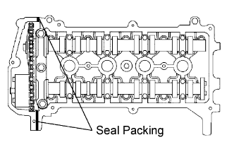 |
Install the gasket onto the cylinder head cover.
Apply seal packing to the 2 locations shown in the illustration.
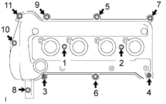 |
Install the cylinder head cover with the 9 bolts, 2 seal washers and 2 nuts.
Using several steps, uniformly tighten the bolts and nuts in the sequence shown in the illustration.
| 35. INSTALL VENTILATION VALVE |
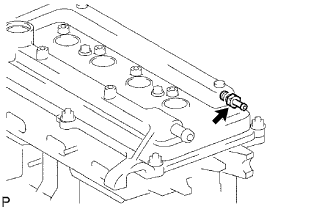 |
Install the ventilation valve onto the cylinder head cover.
| 36. INSTALL OIL FILLER CAP |
Install a new gasket and the oil filler cap.
| 37. INSTALL WATER PUMP PULLEY |
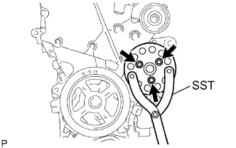 |
Temporarily install the water pump pulley with the 3 bolts.
Using SST, tighten the 3 bolts.
| 38. INSTALL CRANKSHAFT POSITION SENSOR |
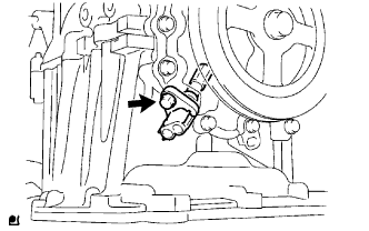 |
Apply a light coat of engine oil to the O-ring on the sensor.
Install the sensor with the bolt.
| 39. INSTALL THERMOSTAT |
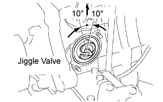 |
Install a new gasket onto the thermostat.
Install the thermostat with the jiggle valve facing upward.
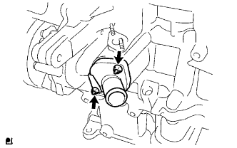 |
Install the water inlet with the 2 nuts.
| 40. INSTALL CAMSHAFT TIMING OIL CONTROL VALVE ASSEMBLY |
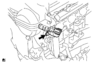 |
Apply a light coat of engine oil to a new O-ring, and install it onto the oil control valve.
Install the oil control valve with the bolt.
| 41. INSTALL CAMSHAFT POSITION SENSOR |
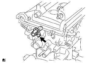 |
Apply engine oil to the O-ring.
Install the sensor with the bolt.
| 42. INSTALL SPARK PLUG |
Using a 16 mm plug wrench, install the 4 spark plugs.