 |
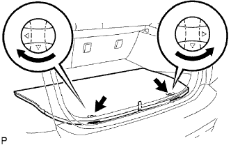
Unlock the 2 washer tank cover knobs, and then remove the rear floor board.
VALVE CLEARANCE > ADJUSTMENT |
| 1. REMOVE REAR NO. 2 FLOOR BOARD |
|
Unlock the 2 washer tank cover knobs, and then remove the rear floor board.
| 2. REMOVE REAR DECK FLOOR BOX |
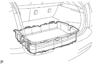 |
Remove the rear deck floor box from the vehicle.
| 3. REMOVE REAR NO. 3 FLOOR BOARD |
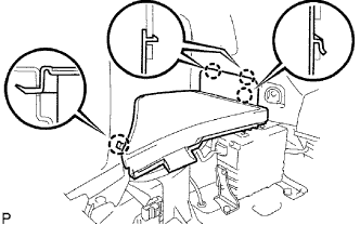 |
Detach the 4 claws, and then remove the floor board.
| 4. DISCONNECT CABLE FROM NEGATIVE BATTERY TERMINAL |
| 5. REMOVE ENGINE UNDER COVER RH |
| 6. REMOVE WIPER ARM HEAD CAP |
| 7. REMOVE FRONT WIPER ARM LH |
Remove the 2 nuts and FR wiper arm LH.
| 8. REMOVE FRONT WIPER ARM RH |
Remove the nut and FR wiper arm RH.
| 9. REMOVE HOOD TO COWL TOP SEAL |
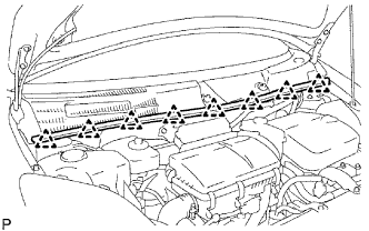 |
Detach the 8 clips and remove the hood to cowl top seal.
| 10. REMOVE COWL TOP VENTILATOR LOUVER LH |
|
Detach the 8 clips and remove the hood to cowl top seal.
| 11. REMOVE COWL TOP VENTILATOR LOUVER RH |
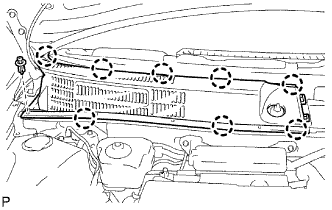 |
Detach the 8 claws and clip, and remove the cowl top ventilator louver RH.
| 12. REMOVE WINDSHIELD WIPER LINK ASSEMBLY |
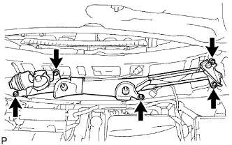 |
Disconnect the connector.
Remove the 5 bolts and wiper motor & link.
| 13. REMOVE FRONT COWL TOP PANEL OUTER |
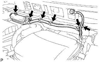 |
Remove the 2 bolts and disconnect the No. 2 engine room relay block.
Remove the 4 wire harness clamps.
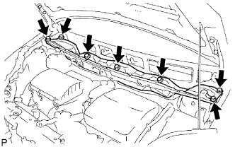 |
Remove the 7 bolts and panel.
| 14. REMOVE RADIATOR SUPPORT OPENING COVER |
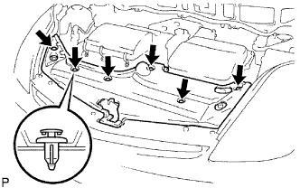 |
Remove the 6 clips and radiator support opening cover.
| 15. REMOVE AIR CLEANER ASSEMBLY |
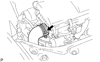 |
Loosen the clamp, then disconnect the No. 1 air cleaner inlet from the air cleaner case.
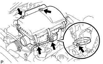 |
Disconnect the intake air flow meter connector, then remove the wire harness clamp.
Loosen the clamp, then remove the 2 bolts and air cleaner assembly.
| 16. DISCONNECT BRAKE MASTER CYLINDER RESERVOIR |
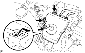 |
Disconnect the connector.
Remove the 2 bolts.
Separate the claw fitting, then suspend the brake master cylinder reservoir with rope.
| 17. REMOVE RESERVOIR BRACKET |
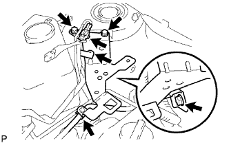 |
Disconnect the hose from the brake master cylinder reservoir bracket.
Remove the 3 bolts and wire harness clamp, then remove the brake master cylinder reservoir bracket.
| 18. REMOVE CYLINDER HEAD COVER |
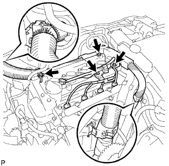 |
Disconnect the fuel injector connector and ignition coil connector.
Remove the 3 bolts and wire harness clamp, then disconnect the wire harness.
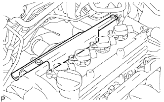 |
Remove the brake master cylinder reservoir cover.
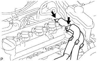 |
Disconnect the ventilation hose and ventilation hose No. 2.
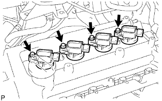 |
Remove the bolt and ignition coil.
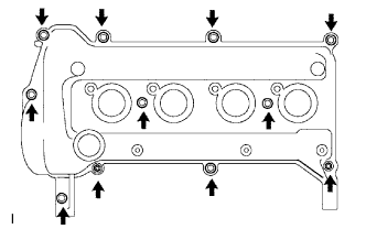 |
Remove the 9 bolts and 2 nuts, then remove the cylinder head cover.
| 19. INSPECT VALVE CLEARANCE |
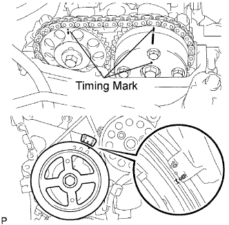 |
Set the No. 1 cylinder to TDC/compression.
Turn the crankshaft pulley until its timing notch and timing mark 0 of the chain cover are aligned.
Check that both timing marks on the camshaft timing sprocket and camshaft timing gear are facing upward as shown in the illustration.
If not, turn the crankshaft 1 complete revolution (360°) and align the marks as above.
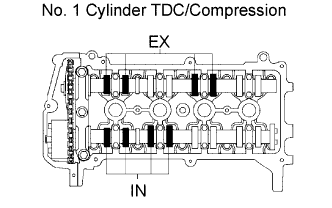 |
Check the valves indicated in the illustration.
Using a feeler gauge, measure the clearance between the valve lifter and camshaft.
| Item | Specified Condition |
| Intake | 0.17 to 0.23 mm (0.007 to 0.009 in.) |
| Exhaust | 0.27 to 0.33 mm (0.011 to 0.013 in.) |
Record any out-of-specification valve clearance measurements. They will be used later to determine the required replacement adjusting shim.
Turn the crankshaft 1 complete revolution until its timing notch and timing mark 0 of the chain cover are aligned.
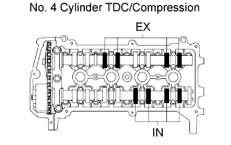 |
Check the valves indicated in the illustration.
Using a feeler gauge, measure the clearance between the valve lifter and camshaft.
| Item | Specified Condition |
| Intake | 0.17 to 0.23 mm (0.007 to 0.009 in.) |
| Exhaust | 0.27 to 0.33 mm (0.011 to 0.013 in.) |
Record any out-of-specification valve clearance measurements. They will be used later to determine the required replacement adjusting shim.
| 20. ADJUST VALVE CLEARANCE |
|
Set the No. 1 cylinder to TDC/compression.
Turn the crankshaft pulley until its timing notch and timing mark 0 of the chain cover are aligned.
Check that both timing marks on the camshaft timing sprocket and valve timing controller assembly are facing upward as shown in the illustration.
If not, turn the crankshaft 1 complete revolution (360°) and align the marks as above.
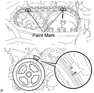 |
Put paint marks on the timing chain where the timing marks of the camshaft timing sprocket and the camshaft timing gear are located.
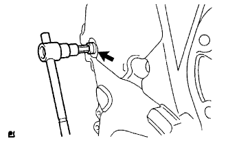 |
Using an 8 mm hexagon wrench, remove the screw plug.
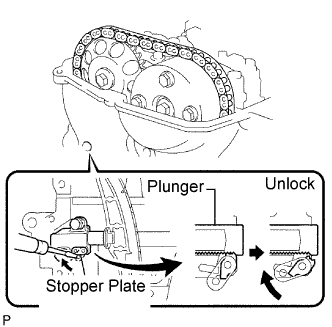 |
Insert a screwdriver into the service hole of the chain tensioner to hold the stopper plate of the chain tensioner at an upward position.
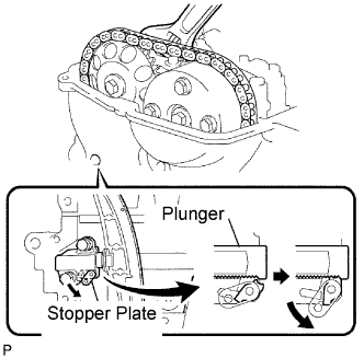 |
Keeping the stopper plate of the chain tensioner lifted, slightly rotate the hexagonal lobe of the No. 2 camshaft to the right with an adjustable wrench so the plunger of the chain tensioner is pushed.
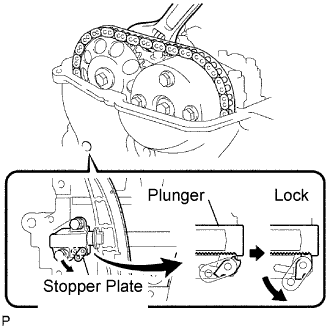 |
Keeping the adjustable wrench installed, remove the screwdriver with the plunger pushed.
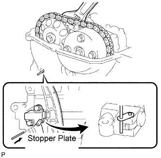 |
Insert a 3.0 mm (0.118 in.) diameter bar into the hole of the stopper plate with the stopper plate of the chain tensioner lowered and locked.
Secure the 3.0 mm (0.118 in.) diameter bar with tape.
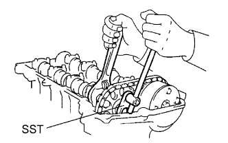 |
Hold the hexagonal lobe of the camshaft No. 2 with the adjustable wrench.
Using SST, loosen the bolt.
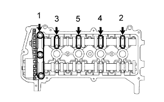 |
Using several steps, uniformly loosen and remove the 11 bearing cap bolts in the sequence shown in the illustration. Then remove the 5 bearing caps.
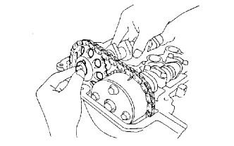 |
Remove the flange bolt with the No. 2 camshaft lifted up. Then detach the No. 2 camshaft and the camshaft timing sprocket.
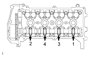 |
Using several steps, uniformly loosen and remove the 8 bearing cap bolts in the sequence shown in the illustration. Then remove the 4 bearing caps.
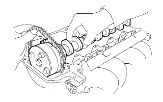 |
Hold the timing chain with one hand, and remove the camshaft and the camshaft timing gear assembly.
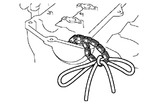 |
Tie the timing chain with a string as shown in the illustration.
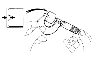 |
Remove the valve lifters.
Using a micrometer, measure the thickness of the removed lifter.
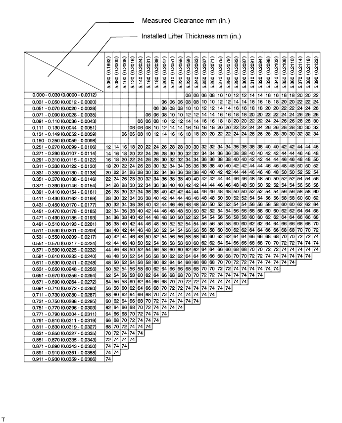
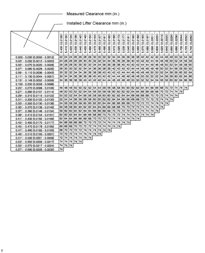
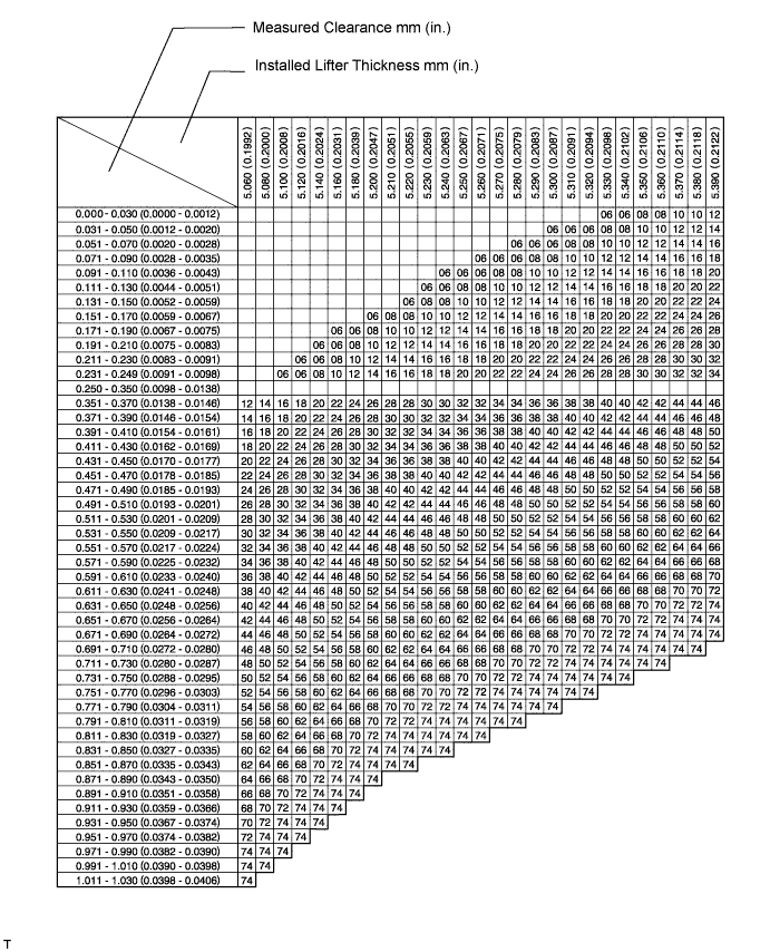
Calculate the thickness of a new lifter so that the valve clearance comes within the specified value.
| A | New lifter thickness |
| B | Used lifter thickness |
| C | Measured valve clearance |
| Item | Thickness |
| Intake | A = B + (C - 0.20 mm (0.008 in.)) |
| Exhaust | A = B + (C - 0.30 mm (0.012 in.)) |
Select a new lifter with the thickness as close to the calculated values as possible.
EXAMPLE: (Intake)
Measured valve clearance = 0.40 mm (0.0158 in.)
0.40 mm (0.0158 in.) - 0.20 mm (0.0079 in.) = 0.20 mm (0.0079 in.)
(Measured - Specification = Excess clearance)
Used lifter measurement = 5.25 mm (0.2067 in.)
0.20 mm (0.0079 in.) + 5.25 mm (0.2067 in.) = 5.45 mm (0.2146 in.)
(Excess clearance + Used lifter = Ideal new lifter)
Closest new lifter = 5.45 mm (0.2146 in.)
Select No. 46 lifter (5.46 mm (0.2150 in.))
Valve lifter selection chart (intake)
Valve lifter selection chart (intake) (continued).
| Lifter No. | Thickness | Lifter No. | Thickness | Lifter No. | Thickness |
| 06 | 5.060 mm (0.1992 in.) | 30 | 5.300 mm (0.2087 in.) | 54 | 5.540 mm (0.2181 in.) |
| 08 | 5.080 mm (0.2000 in.) | 32 | 5.320 mm (0.2094 in.) | 56 | 5.560 mm (0.2189 in.) |
| 10 | 5.100 mm (0.2008 in.) | 34 | 5.340 mm (0.2102 in.) | 58 | 5.580 mm (0.2197 in.) |
| 12 | 5.120 mm (0.2016 in.) | 36 | 5.360 mm (0.2110 in.) | 60 | 5.600 mm (0.2205 in.) |
| 14 | 5.140 mm (0.2024 in.) | 38 | 5.380 mm (0.2118 in.) | 62 | 5.620 mm (0.2213 in.) |
| 16 | 5.160 mm (0.2031 in.) | 40 | 5.400 mm (0.2126 in.) | 64 | 5.640 mm (0.2220 in.) |
| 18 | 5.180 mm (0.2039 in.) | 42 | 5.420 mm (0.2134 in.) | 66 | 5.660 mm (0.2228 in.) |
| 20 | 5.200 mm (0.2047 in.) | 44 | 5.440 mm (0.2142 in.) | 68 | 5.680 mm (0.2236 in.) |
| 22 | 5.220 mm (0.2055 in.) | 46 | 5.460 mm (0.2150 in.) | 70 | 5.700 mm (0.2244 in.) |
| 24 | 5.240 mm (0.2063 in.) | 48 | 5.480 mm (0.2157 in.) | 72 | 5.720 mm (0.2252 in.) |
| 26 | 5.260 mm (0.2071 in.) | 50 | 5.500 mm (0.2165 in.) | 74 | 5.740 mm (0.2260 in.) |
| 28 | 5.280 mm (0.2079 in.) | 52 | 5.520 mm (0.2173 in.) | - | - |
Valve lifter selection chart (exhaust).
Valve selection chart (exhaust) (continued).
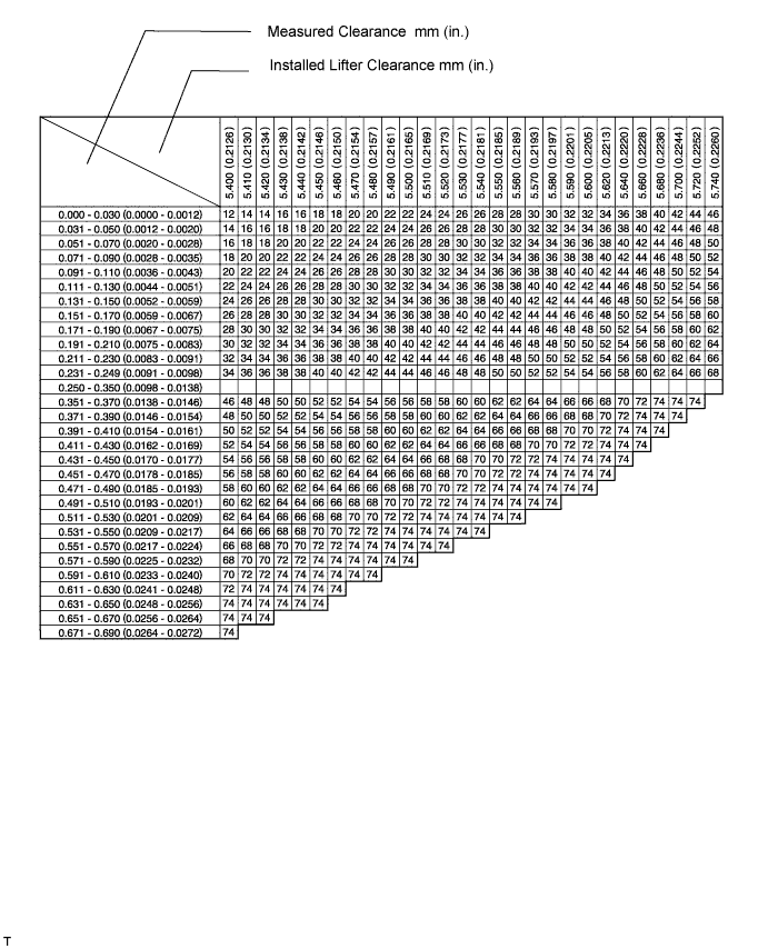
| Lifter No. | Thickness | Lifter No. | Thickness | Lifter No. | Thickness |
| 06 | 5.060 mm (0.1992 in.) | 30 | 5.300 mm (0.2087 in.) | 54 | 5.540 mm (0.2181 in.) |
| 08 | 5.080 mm (0.2000 in.) | 32 | 5.320 mm (0.2094 in.) | 56 | 5.560 mm (0.2189 in.) |
| 10 | 5.100 mm (0.2008 in.) | 34 | 5.340 mm (0.2102 in.) | 58 | 5.580 mm (0.2197 in.) |
| 12 | 5.120 mm (0.2016 in.) | 36 | 5.360 mm (0.2110 in.) | 60 | 5.600 mm (0.2205 in.) |
| 14 | 5.140 mm (0.2024 in.) | 38 | 5.380 mm (0.2118 in.) | 62 | 5.620 mm (0.2213 in.) |
| 16 | 5.160 mm (0.2031 in.) | 40 | 5.400 mm (0.2126 in.) | 64 | 5.640 mm (0.2220 in.) |
| 18 | 5.180 mm (0.2039 in.) | 42 | 5.420 mm (0.2134 in.) | 66 | 5.660 mm (0.2228 in.) |
| 20 | 5.200 mm (0.2047 in.) | 44 | 5.440 mm (0.2142 in.) | 68 | 5.680 mm (0.2236 in.) |
| 22 | 5.220 mm (0.2055 in.) | 46 | 5.460 mm (0.2150 in.) | 70 | 5.700 mm (0.2244 in.) |
| 24 | 5.240 mm (0.2063 in.) | 48 | 5.480 mm (0.2157 in.) | 72 | 5.720 mm (0.2252 in.) |
| 26 | 5.260 mm (0.2071 in.) | 50 | 5.500 mm (0.2165 in.) | 74 | 5.740 mm (0.2260 in.) |
| 28 | 5.280 mm (0.2079 in.) | 52 | 5.520 mm (0.2173 in.) | - | - |
Reinstall the selected valve lifters.
Apply a light coat of engine oil to the camshaft journals.
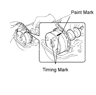 |
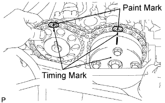
Install the timing chain onto the camshaft timing gear with the paint mark and the timing mark aligned as shown in the illustration.
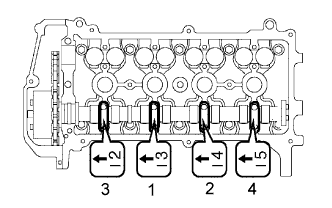 |
Examine the front marks and numbers, and tighten the bolts in the sequence shown in the illustration.
 |
Hold the timing chain, and align the timing mark on the camshaft timing sprocket with the paint mark of the timing chain.
|
Align the alignment pin hole on the camshaft timing sprocket with the alignment pin of the camshaft, and install the sprocket into the camshaft.
Temporarily install the timing sprocket bolt.
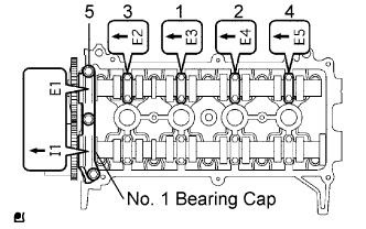 |
Examine the front marks and numbers, and tighten the bolts in the sequence shown in the illustration.
Install the No. 1 bearing cap.
|
Hold the hexagonal lobe of the No. 2 camshaft with the adjustable wrench.
Using SST, tighten the bolt.
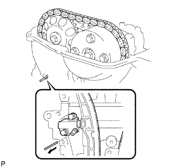 |
Remove the bar from the timing chain tensioner.
|
Turn the crankshaft pulley until its timing notch and timing mark 0 of the chain cover are aligned.
Check that all the pairs of the timing marks are aligned.
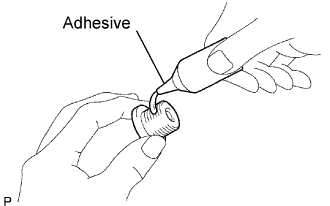 |
Apply seal packing to 2 or 3 threads of the screw plug end.
|
Using an 8 mm hexagon wrench, install the screw plug.
| 21. INSTALL CYLINDER HEAD COVER |
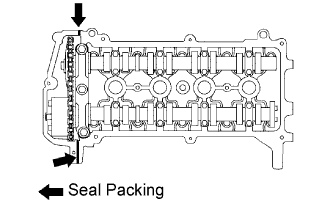 |
Apply seal packing to the 2 locations shown in the illustration, then install the cylinder head cover.
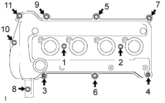 |
Install the cylinder head cover with the 9 bolts and 2 nuts.
Using several steps, tighten the bolts and nuts to the specified torque in the sequence shown in the illustration.
|
Install the ignition coil with the bolt.
|
Install the brake master cylinder reservoir cover to the cylinder head cover.
|
Install the wire harness and brake master cylinder reservoir cover with the 3 bolts.
Connect the fuel injector connector and ignition coil connector.
| 22. INSTALL RESERVOIR BRACKET |
|
Install the reservoir bracket with the 3 bolts and connect the wire harness clamp.
| 23. INSTALL BRAKE MASTER CYLINDER RESERVOIR |
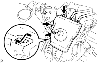 |
Attach the claw and install the master cylinder reservoir with the 2 bolts.
Connect the connector.
| 24. INSTALL AIR CLEANER ASSEMBLY |
|
Install the air cleaner with the 2 bolts and tighten the clamp.
Connect the MAF meter connector and clamp.
|
Connect the No. 1 air inlet, and then tighten the clamp.
| 25. INSTALL FRONT COWL TOP PANEL OUTER |
|
Install the panel with the 7 bolts.
|
Connect the 4 wire harness clamps.
Install the No. 2 engine room relay block with the 2 bolts.
| 26. INSTALL WINDSHIELD WIPER LINK ASSEMBLY |
|
Install the windshield wiper motor & link with the 5 bolts.
Connect the connector.
| 27. INSTALL COWL TOP VENTILATOR LOUVER RH |
| 28. INSTALL COWL TOP VENTILATOR LOUVER LH |
| 29. INSTALL HOOD TO COWL TOP SEAL |
| 30. INSTALL FRONT WIPER ARM LH |
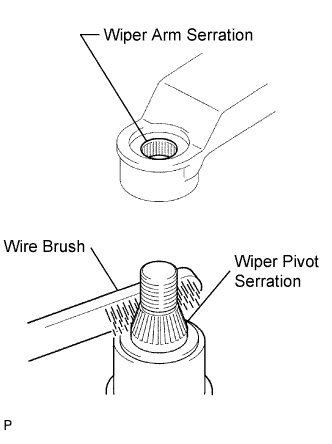 |
Clean the wiper arm serration with a round file or equivalent (when reinstalling).
Clean the wiper pivot serration with a wire brush.
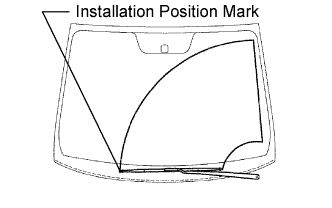 |
Install the front wiper arm LH with the nut so that the front wiper blade comes to the position shown in the illustration.
| 31. INSTALL FRONT WIPER ARM RH |
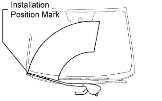 |
Clean the wiper arm serration with a round file or equivalent (when reinstalling).
Clean the wiper pivot serration with a wire brush.
Install the front wiper arm RH with the 2 nuts so that the front wiper blade comes to the position shown in the illustration.
Operate the front wipers while spraying water or washer fluid on the windshield glass. Ensure that the wipers function properly and there is no interference with the body.
| 32. INSTALL WIPER ARM HEAD CAP |
| 33. INSPECT FOR OIL LEAK |
| 34. INSTALL RADIATOR SUPPORT OPENING COVER |
|
Install the opening cover with the 6 clips.
| 35. REMOVE ENGINE UNDER COVER RH |
| 36. CONNECT CABLE TO NEGATIVE BATTERY TERMINAL |
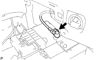 |
Connect the battery negative cable, and then tighten the nut.
| 37. INSTALL REAR NO. 3 FLOOR BOARD |
|
Install the floor board, and then attach the 4 claws.
| 38. INSTALL REAR DECK FLOOR BOX |
|
Install the rear deck floor box to the vehicle.
| 39. INSTALL NO. 2 REAR FLOOR BOARD |
|
Install the floor board, and then lock the 2 cover knobs.
| 40. PERFORM INITIALIZATION |
Perform initialization (Click here).