 |
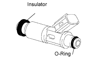
Install new insulators onto each fuel injector.
CYLINDER HEAD > INSTALLATION |
| 1. INSTALL FUEL INJECTOR |
|
Install new insulators onto each fuel injector.
Apply a light coat of spindle oil or gasoline to new O-rings and install them onto each fuel injector.
Apply a light coat of spindle oil or gasoline to the place where a delivery pipe comes into contact with the O-ring.
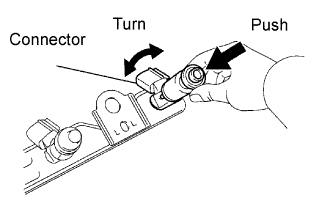 |
While turning the injector clockwise and counterclockwise, install it to the delivery pipe.
| 2. INSTALL FUEL DELIVERY PIPE |
Install the 2 spacers onto the cylinder head.
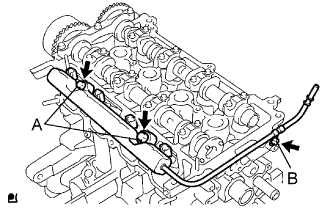 |
Install the fuel delivery pipe and 4 fuel injectors together.
| 3. INSTALL ENGINE COOLANT TEMPERATURE SENSOR |
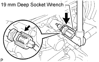 |
Using a 19 mm deep socket wrench, install a new gasket and the sensor.
Connect the sensor connector.
| 4. INSTALL NOISE FILTER |
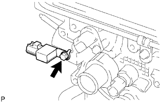 |
Install the noise filter with the bolt.
| 5. INSTALL EXHAUST MANIFOLD |
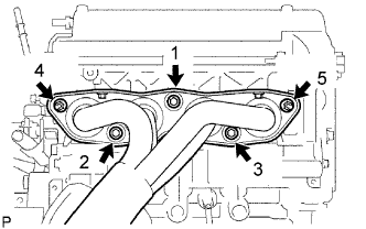 |
Install a new gasket, then install the exhaust manifold.
Tighten the 3 bolts and 2 nuts in the sequence shown in the illustration.
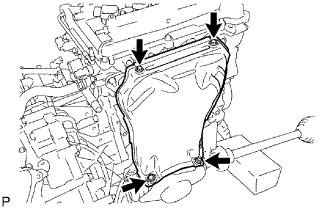 |
Install the exhaust manifold insulator with the 4 bolts.
| 6. INSTALL INTAKE MANIFOLD |
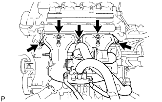 |
Install a new gasket, then install the intake manifold with the 3 bolts and 2 nuts.
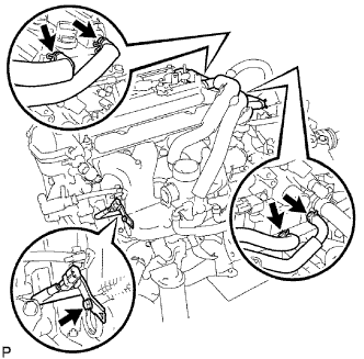 |
Connect the water by-pass hose.
Connect the ventilation hose.
Install the knock control sensor with bracket with the bolt.
| 7. INSTALL CYLINDER HEAD GASKET |
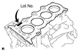 |
Place a new head gasket on the cylinder block with the Lot No. facing upward.
| 8. INSTALL CYLINDER HEAD |
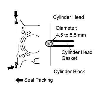 |
Apply seal packing as shown in the illustration.
Apply a light coat of engine oil to the threads of the cylinder head bolts.
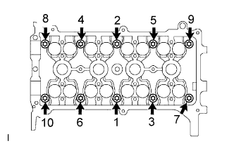 |
Using several steps, install and tighten the 10 cylinder head bolts and plate washers uniformly with an 8 mm bi-hexagon wrench in the sequence shown in the illustration.
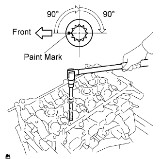 |
Mark the front of the cylinder head bolt with paint.
Retighten the cylinder head bolts by an additional 90° and then another 90°, as shown in the illustration.
Check that the paint mark is now 180° opposite to the front.
| 9. INSTALL CAMSHAFT |
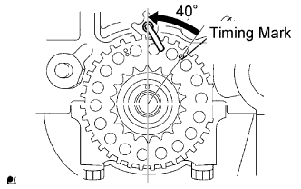 |
Apply engine oil to the cam and cylinder head journals.
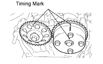 |
Place the camshaft and No. 2 camshaft on the cylinder head with the timing mark on the camshaft timing gear facing upward.
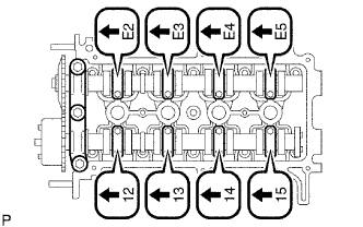 |
Check the front marks and numbers on the No. 1 and No. 2 camshaft bearing caps, then temporarily install them.
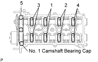 |
Uniformly tighten the No. 2 camshaft bearing caps in several steps in the sequence shown in the illustration.
Install the No. 1 camshaft bearing cap.
| 10. INSTALL OIL DIPSTICK GUIDE |
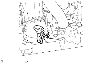 |
Install the dipstick guide with the bolt.
Connect the hose.
| 11. INSTALL NO. 1 WATER BY-PASS PIPE |
Connect the water by-pass pipe with the bolt.
| 12. CONNECT HOSES |
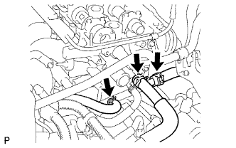 |
Connect the hoses shown in the illustration.
| 13. REMOVE RADIATOR INLET HOSE |
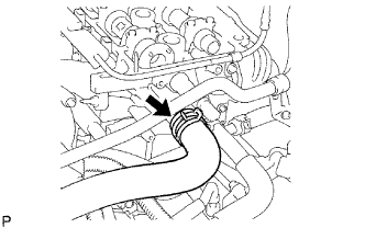 |
Connect the radiator inlet hose.
| 14. CONNECT FUEL MAIN TUBE |
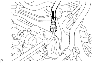 |
Push the fuel tube into the fuel delivery pipe until it makes a "click" sound.
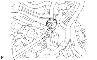 |
Install the fuel pipe clamp.
| 15. CONNECT WIRE HARNESS |
Connect the connectors and wire harnesses shown in the illustration.
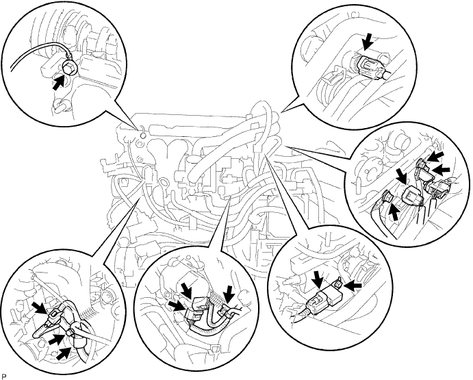
| 16. INSTALL CHAIN |
Install the chain to the engine .
| 17. INSTALL INVERTER WITH CONVERTER ASSEMBLY |
Install the inverter with converter to the vehicle .
| 18. INSTALL FRONT EXHAUST ASSEMBLY |
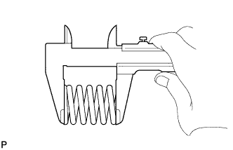 |
Using a vernier caliper, measure the free length of the compression spring.
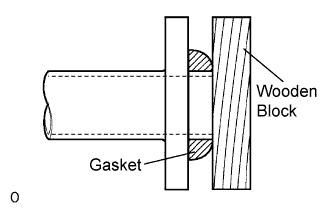 |
Using a plastic-faced hammer and wooden block, tap in a new gasket until its surface is flush with the exhaust manifold.
Connect the 2 exhaust pipe supports, and install the exhaust pipe.
Install the 2 compression springs and 2 bolts.
| 19. INSTALL SERVICE PLUG GRIP |
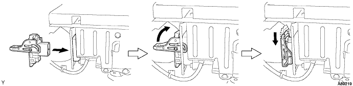
Joint the service plug grip with the HV battery.
While pushing the service plug grip to the right, rotate the lever to the right.
Slide the lever down to lock the service plug grip in place.
| 20. CONNECT CABLE TO NEGATIVE BATTERY TERMINAL |
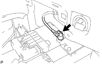 |
Connect the battery negative cable, and then tighten the nut.
| 21. INSPECT FOR FUEL LEAK |
Check that there are no leaks in the fuel system while fuel pressure is applied.
| 22. INSTALL REAR NO. 3 FLOOR BOARD |
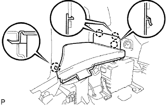 |
Install the floor board, and then attach the 4 claws.
| 23. INSTALL REAR DECK FLOOR BOX |
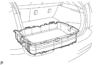 |
Install the rear deck floor box to the vehicle.
| 24. INSTALL REAR NO. 2 FLOOR BOARD |
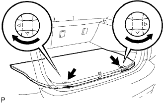 |
Install the floor board, and then lock the 2 cover knobs.
| 25. PERFORM INITIALIZATION |
Perform initialization (Click here).