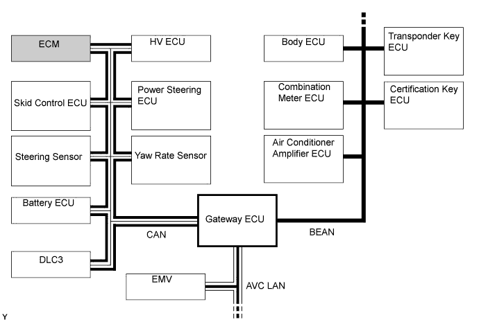
Transmit To
| Receive From
| Signal
| Communication Line
|
HV ECU
| ECM
| - Inspection mode signal
- MIL illumination requirement
- Shift position information
- Ready state
- Starter ON
| CAN
|
ECM
| HV ECU
| - Ambient temperature
- Intake air temperature
- Radiator fan drive
- Engine warm-up requirement
- Engine rpm
| CAN
|
ECM
| Battery ECU
| - Engine rpm
| CAN
|
ECM
| Power Steering ECU
| - Inspection mode
| CAN
|
ECM
| Skid Control ECU
| - Inspection mode
| CAN
|
ECM
| Body ECU
| - Inspection mode
- Engine rpm
| BEAN, CAN
|
Combination Meter ECU
| ECM
| - Fuel level
| BEAN, CAN
|
ECM
| Combination Meter ECM
| - Engine coolant temperature
- Engine rpm
- Injection volume
- Inspection mode
- Engine oil pressure switch
| BEAN, CAN
|
ECM
| Air Conditioner Amplifier ECU
| - Engine coolant temperature
- Engine rpm
- Ambient temperature
- Coolant heat storage water valve close
| BEAN, CAN
|
ECM
| Certification ECU
| - Engine rpm
| BEAN, CAN
|
ECM
| EMV
| - Engine coolant temperature
- Inspection mode
- Engine oil pressure switch
| ACV LAN, CAN
|