Home › ENGINE › 1NZ-FXE ENGINE CONTROL SYSTEM › SFI SYSTEM

DTC    P0120    Throttle / Pedal Position Sensor / Switch "A" Circuit Malfunction

DTC    P0122    Throttle / Pedal Position Sensor / Switch "A" Circuit Low Input

DTC    P0123    Throttle / Pedal Position Sensor / Switch "A" Circuit High Input

DTC    P0220    Throttle / Pedal Position Sensor / Switch "B" Circuit

DTC    P0222    Throttle / Pedal Position Sensor / Switch "B" Circuit Low Input

DTC    P0223    Throttle / Pedal Position Sensor / Switch "B" Circuit High Input

DTC    P2135    Throttle / Pedal Position Sensor / Switch "A" / "B" Voltage Correlation

for Preparation Click here


DESCRIPTION

HINT:
  1. This electrical throttle system does not use a throttle cable.
  2. This is the troubleshooting procedure of the throttle position sensor.
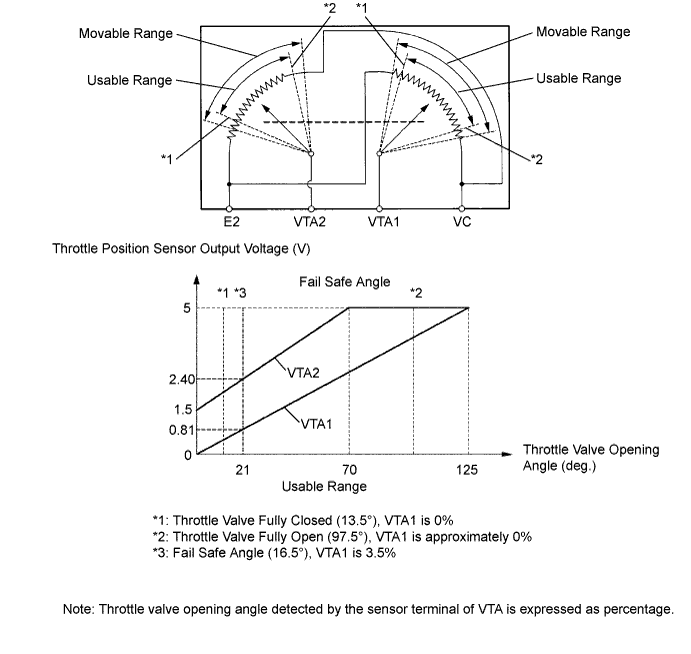
The throttle position sensor is mounted on the throttle body and it has 2 sensor terminals to detect the throttle opening angle and malfunctions of the throttle position sensor itself.
The voltage applied to terminals VTA and VTA2 of the ECM changes between 0 V and 5 V in proportion to the opening angle of the throttle valve. The VTA is a signal to indicate the actual throttle valve opening angle which is used for the engine control, and the VTA2 is a signal to indicate the information about the opening angle which is used for detecting malfunctions of the sensor.
The ECM judges the current opening angle of the throttle valve from these signals input from terminals VTA and VTA2, and the ECM controls the throttle motor to make the throttle valve angle properly in response to the driving condition.
When a malfunction is detected, the throttle valve is locked at a certain opening angle. Also, the whole electronically controlled throttle operation is canceled until the system returns to normal and the power switch is turned OFF.


A071013E01


DTC No.
DTC Detection Condition
Trouble Area
-
Condition of DTC P0120, P0122, P0123, P0220, P0222 or P0223 continues for 2 seconds or more when idling
-
P0120
Detection conditions for DTCs P0122 and P0123 are not satisfied but condition (a) is satisfied
(a) VTA is 0.2 V or less, or 4.535 V or more
  1. Open or short in throttle position sensor circuit
  2. Throttle position sensor (built into throttle body)
  3. ECM
P0122
VTA is 0.2 V or less
  1. Throttle position sensor (built into throttle body)
  2. Short in VTA1 circuit
  3. Open in VC circuit
  4. ECM
P0123
VTA is 4.535 V or more
  1. Throttle position sensor (built into throttle body)
  2. Open in VTA1 circuit
  3. Open in E2 circuit
  4. Short between VC and VTA1 circuits
  5. ECM
P0220
Detection conditions for DTCs P0222 and P0223 are not satisfied but the following condition is satisfied
(a) VTA2 is 1.75 V or less, or VTA2 is 4.8 V or more
  1. Open or short in throttle position sensor circuit
  2. Throttle position sensor (built into throttle body)
  3. ECM
P0222
VTA2 is 1.75 V or less
  1. Throttle position sensor (built into throttle body)
  2. Short in VTA2 circuit
  3. Open in VC circuit
  4. ECM
P0223
VTA2 is 4.8 V or more when VTA is 0.2 or more and 2.02 V or less
  1. Throttle position sensor (built into throttle body)
  2. Open in VTA2 circuit
  3. Open in E2 circuit
  4. Short between VC and VTA2 circuits
  5. ECM
P2135
Condition (a) continues for 0.5 seconds or more, or condition (b) continues for 0.4 seconds or more:
(a) Difference between VTA and VTA2 is 0.02 V or less
(b) VTA is 0.2 V or less and VTA2 is 1.75 V or less
  1. Short between VTA1 and VTA2 circuits
  2. Throttle position sensor (built into throttle body)
  3. ECM

NOTICE:
When a malfunction is detected, the throttle valve is locked at a certain opening angle. Also, the whole electronically controlled throttle operation is canceled until the system returns to normal and the power switch is turned OFF.


HINT:
  1. After confirming DTCs, confirm condition of the throttle valve opening angle (THROTTLE POS) and the closed throttle position switch (THROTTLE POS #2) using Techstream.
  2. THROTTLE POS means the VTA1 signal (expressed as percentage), and THROTTLE POS#2 means the VTA2 signal (expressed as volts).

Tester display
Accelerator pedal released
Accelerator pedal depressed
THROTTLE POS
8 to 20%
64 to 96%
THROTTLE POS #2
1.5 to 2.9 V
3.5 to 5.5 V


MONITOR DESCRIPTION

The ECM uses the throttle position sensor to monitor the throttle valve opening angle.
(a) There is a specific voltage difference between VTA1 and VTA2 for each throttle opening angle.
(b) VTA1 and VTA2 each has a specific voltage operating range.
(c) VTA1 and VTA2 should never be close to the same voltage level.
If the difference between VTA1 and VTA2 is incorrect (a), the ECM interprets this as a fault and will set a DTC.
If VTA1 or VTA2 is out of the normal operating range (b), the ECM interprets this as a fault and will set a DTC.
If VTA1 is within 0.02 V of VTA2 (c), the ECM interprets this as a short circuit in the throttle position sensor system and will set a DTC.

MONITOR STRATEGY


Related DTCs
P0120: Throttle position sensor (sensor 1) range check (fluttering)
P0122: Throttle position sensor (sensor 1) range check (low voltage)
P0123: Throttle position sensor (sensor 1) range check (high voltage)
P0220: Throttle position sensor (sensor 2) range check (fluttering)
P0222: Throttle position sensor (sensor 2) range check (low voltage)
P0223: Throttle position sensor (sensor 2) range check (high voltage)
P2135: Throttle position sensor range check (correlation)
Required sensors/components
Throttle position sensor
Frequency of operation
Continuous
Duration
2 seconds: P0120, P0122, P0123, P0220, P0222, P0223 (Accelerator pedal ON)
10 seconds: P0120, P0122, P0123, P0220, P0222, P0223 (Accelerator pedal OFF)
0.5 seconds: P2135
MIL operation
Immediately
Sequence of operation
None

TYPICAL ENABLING CONDITIONS


The monitor will run whenever the following DTCs are not present
None

TYPICAL MALFUNCTION THRESHOLDS


P0120: 
VTA1 voltage
0.2 V or less or 4.535 V or more

P0122: 
VTA1 voltage
0.2 V or less

P0123: 
VTA1 voltage
4.535 V or more

P0220: 
VTA2 voltage
1.75 V or less or 4.8 V or more

P0222: 
VTA2 voltage
1.75 V or less

P0223: 
VTA2 voltage
4.8 V or more (VTA voltage is 0.2 and 2.02 V)

P2135: 
Different between VTA1 and VTA2 voltage
0.02 V or less
Both of the following conditions are met:
(a) and (b)
(a) VTA1 voltage
0.2 V or less
(b) VTA2 voltage
1.75 V or less

COMPONENT OPERATING RANGE


Throttle position sensor VTA1 voltage
0.2 to 4.535 V
Throttle position sensor VTA2 voltage
1.75 to 4.8 V

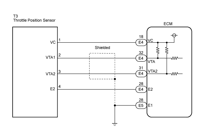
WIRING DIAGRAM


A151888E01


INSPECTION PROCEDURE

HINT:
  1. If DTCs related to different systems that have terminal E2 as the ground terminal are output simultaneously, terminal E2 may have an open circuit.
  2. Read freeze frame data using Techstream. The ECM records vehicle and driving condition information as freeze frame data the moment a DTC is stored. When troubleshooting, freeze frame data can be helpful in determining whether the vehicle was running or stopped, whether the engine was warmed up or not, whether the air/fuel ratio was lean or rich, as well as other data recorded at the time of a malfunction.

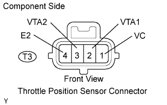
1.INSPECT THROTTLE POSITION SENSOR (RESISTANCE)


    A054410E01
  1. Disconnect the T3 throttle position sensor connector.

  1. Measure the resistance between the terminals of the throttle position sensor.

    Standard resistance:
    Tester Connection
    Specified Condition
    1 (VC) - 4 (E2)
    1.2 to 3.2 kΩ at 20°C (68°F)
    2 (VTA1) - 4 (E2)
    1.8 to 10.5 kΩ at 20°C (68°F)
    3 (VTA2) - 4 (E2)
    1.8 to 10.5 kΩ at 20°C (68°F)


NG
REPLACE THROTTLE W/MOTOR BODY ASSEMBLY
OK


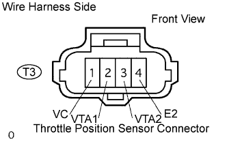
2.CHECK HARNESS AND CONNECTOR (ECM - THROTTLE POSITION SENSOR)


    A061997E01
  1. Disconnect the T3 throttle position sensor connector.


    A065743E69
  1. Disconnect the ECM E4 connector.

  1. Measure the resistance according to the value(s) in the table below.

    Standard resistance (Check for open):
    Tester Connection
    Specified Condition
    T3-1 (VC) - E4-18 (VC)
    Below 1 Ω
    T3-2 (VTA1) - E4-32 (VTA)
    Below 1 Ω
    T3-3 (VTA2) - E4-31 (VTA2)
    Below 1 Ω
    T3-4 (E2) - E4-28 (E2)
    Below 1 Ω

    Standard resistance (Check for short):
    Tester Connection
    Specified Condition
    E4-18 (VC) - E4-28 (E2)
    10 kΩ or higher
    E4-32 (VTA) - E4-28 (E2)
    10 kΩ or higher
    E4-31 (VTA2) - E4-28 (E2)
    10 kΩ or higher

  1. Reconnect the ECM connector.

  1. Reconnect the throttle position sensor connector.


NG
REPAIR OR REPLACE HARNESS OR CONNECTOR
OK


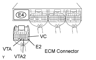
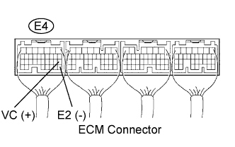
3.CHECK ECM (VC - E2)


    A124045E05
  1. Turn the power switch ON (IG).

  1. Measure the voltage between terminals VC and E2 of the ECM connector.

    Standard voltage:
    Tester Connection
    Specified Condition
    E4-18 (VC) - E4-28 (E2)
    4.5 to 5.5 V


NG
REPLACE ECM
OK

REPLACE THROTTLE W/MOTOR BODY ASSEMBLY