 |
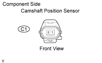
Disconnect the C1 camshaft position sensor connector.
DTC P0340 Camshaft Position Sensor Circuit Malfunction |
DTC P0341 Camshaft Position Sensor "A" Circuit Range / Performance (Bank 1 or Single Sensor) |
| DTC No. | DTC Detection Condition | Trouble Area |
| P0340 | No camshaft position sensor signal to ECM at engine speed of 600 rpm or more (1 trip detection logic) |
|
| P0341 | While crankshaft rotates twice, camshaft position sensor signal is input to ECM 12 times or more (1 trip detection logic) HINT: Under normal condition, the camshaft position sensor signal is input into the ECM 3 times per 2 engine revolutions |
|
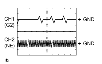
| Item | Contents |
| Terminal | CH1: G2 - NE- CH2: NE+ - NE- |
| Equipment Setting | 5 V/DIV., 20 ms/DIV. |
| Condition | During cranking or idling |
| Related DTCs | P0340: Camshaft position sensor (bank 1) range check or rationality P0341: Camshaft position sensor (bank 1) range check or rationality |
| Required sensors/components | Main: Camshaft position sensor Related: Crankshaft position sensor, engine speed sensor |
| Frequency of operation | Continuous |
| Duration | 5 seconds |
| MIL operation | Immediately |
| Sequence of operation | None |
| The monitor will run whenever the following DTCs are not present | None |
| Engine speed | 600 rpm or more |
| The monitor will run whenever the following DTCs are not present | None |
| Engine rotating signal from HV ECU | HV ECU judges that engine is running |
| Engine revolution angle | 720°CA* |
| Crankshaft/camshaft synchronization | Not synchronized (judged by comparing the crankshaft position with the camshaft position) |
| Camshaft position sensor signal | No input in appropriate timing |
| Crankshaft/Camshaft synchronization | Not synchronized |
| Camshaft position sensor count | 12 or more / 720°CA* (= 2 engine revolutions) |
| Camshaft position sensor signal input every 720°CA | 3 times |
| 1.INSPECT CAMSHAFT POSITION SENSOR (RESISTANCE) |
|
Disconnect the C1 camshaft position sensor connector.
Measure the resistance between the terminals of the camshaft position sensor connector.
| Tester Connection | Specified Condition |
| 1 - 2 | 1,630 to 2,740 Ω at cold |
| 1 - 2 | 2,065 to 3,225 Ω at hot |
Reconnect the camshaft position sensor connector.
|
| ||||
| OK | |
 |
| 2.CHECK HARNESS AND CONNECTOR (CAMSHAFT POSITION SENSOR - ECM) |
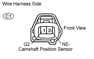 |
Disconnect the C1 camshaft position sensor connector.
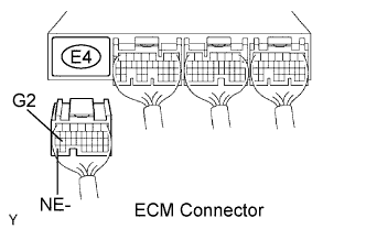 |
Disconnect the E4 ECM connector.
Measure the resistance according to the value(s) in the table below.
| Tester Connection | Specified Condition |
| C1-1 (G2) - E4-26 (G2) | Below 1 Ω |
| C1-2 (NE-) - E4-34 (NE-) | Below 1 Ω |
| Tester Connection | Specified Condition |
| C1-1 (G2) or E4-26 (G2) - Body ground | 10 kΩ or higher |
| C1-2 (NE-) or E4-34 (NE-) - Body ground | 10 kΩ or higher |
Reconnect the camshaft position sensor connector.
Reconnect the ECM connector.
|
| ||||
| OK | |
|
| 3.CHECK SENSOR INSTALLATION (CAMSHAFT POSITION SENSOR) |
Check that the camshaft position sensor is properly installed.
|
| ||||
| OK | |
|
| 4.CHECK CAMSHAFT |
Remove the camshaft.
Check the camshaft lobes.
|
| ||||
| OK | ||
 | ||
| ||
