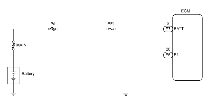
DTC P0560 System Voltage |
| DTC No. | DTC Detection Condition | Trouble Area |
| P0560 | Open in back-up power source circuit |
|
| Related DTCs | P0560: System voltage malfunction |
| Required sensors/components (main) | ECM |
| Frequency of operation | Continuous |
| Duration | 3 seconds |
| MIL operation | Immediately |
| Sequence of operation | None |
| The monitor will run whenever the following DTCs are not present | None |
| Stand-by RAM | Initialized |
| Battery voltage | Less than 3.5 V |
| 1.CHECK FUSE (EFI FUSE) |
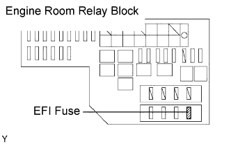 |
Remove the EFI fuse from the engine room relay block.
Measure the resistance of the EFI fuse.
Reinstall the EFI fuse.
|
| ||||
| OK | |
 |
| 2.CHECK ECM (BATTERY VOLTAGE) |
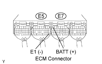 |
Measure the voltage between the specified terminals of the E5 and E7 ECM connectors.
| Tester Connection | Specified Condition |
| E7-6 (BATT) - E5-28 (E1) | 9 to 14 V |
|
| ||||
| NG | |
|
| 3.CHECK HARNESS AND CONNECTOR (ECM - EFI FUSE, EFI FUSE - BATTERY) |
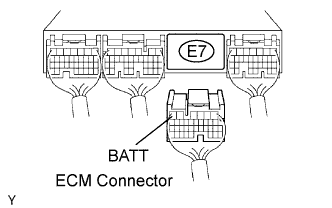 |
Check the harness and the connectors between the EFI fuse and the ECM connector.
Remove the integration relay from the engine room relay block.
Disconnect the E7 ECM connector.
Measure the resistance according to the value(s) in the table below.
| Tester Connection | Specified Condition |
| 2 (EFI fuse) - E7-6 (BATT) | Below 1 Ω |
| Tester Connection | Specified Condition |
| 2 (EFI fuse) or E7-6 (BATT) - Body ground | 10 kΩ or higher |
Reinstall the integration relay.
Reconnect the ECM connector.
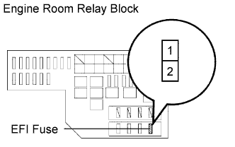 |
Check the harness and the connectors between the EFI fuse and the battery.
Remove the integration relay from the engine room relay block.
Disconnect the positive battery terminal.
Measure the resistance according to the value(s) in the table below.
| Tester Connection | Specified Condition |
| Battery positive terminal - 1 (EFI fuse) | Below 1 Ω |
| Tester Connection | Specified Condition |
| Battery positive terminal or 1 (EFI fuse) - Body ground | 10 kΩ or higher |
Reinstall the integration relay.
Reconnect the positive battery terminal.
|
| ||||
| OK | ||
 | ||
| ||
