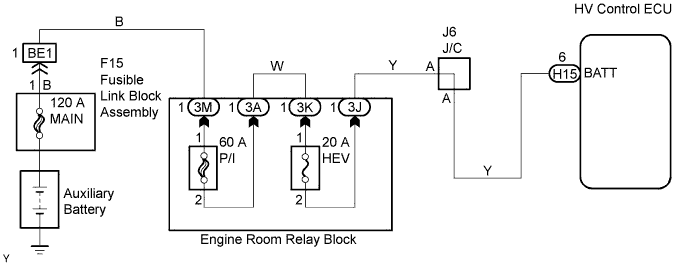
DTC P0560-117 System Voltage |
| DTC No. | INF Code | DTC Detection Condition | Trouble Area |
| P0560 | 117 | HV control ECU back-up power source circuit malfunction |
|
| Related DTCs | P0560 (INF 117): Battery signal malfunction |
| Required sensor / components | Main: Back-up power source circuit Sub: Hybrid vehicle control ECU |
| Frequency of operation | Continuous |
| Duration | 3 seconds |
| MIL operation | Immediate after next power switch ON (IG) |
| Sequence of operation | None |
| The monitor will run whenever the following DTCs are not present | TOYOTA's intellectual property |
| A/D converter | Normal |
| Auxiliary battery voltage | More than 9.5 V |
| Condition (a) or (b) is met | - |
| (a) Input voltage for BATT signal | Less than 2.5 V |
| (b) Abnormal flag for SRAM | ON |
| Auxiliary battery voltage | Between 9 and 14 V |
| 1.INSPECT FUSE (HEV 20 A) |
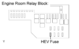 |
Remove the HEV fuse from the engine room relay block.
Measure the resistance of the HEV fuse.
Reinstall the HEV fuse.
|
| ||||
| OK | |
 |
| 2.CHECK HARNESS AND CONNECTOR (HYBRID VEHICLE CONTROL ECU - AUXILIARY BATTERY) |
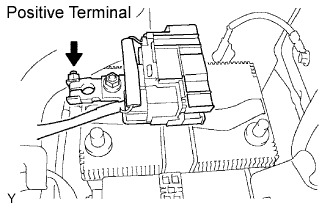
Disconnect the negative auxiliary battery terminal.
 |
Disconnect the positive auxiliary battery terminal.
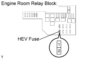 |
Remove the HEV fuse from the engine room relay block.
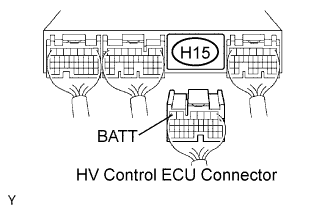 |
Disconnect the H15 HV control ECU connector.
Measure the resistance between the wire harness side connectors.
| Tester Connection | Specified Condition |
| BATT (H15-6) - HEV fuse (2) | Below 1 Ω |
Measure the resistance between the wire harness side connectors.
| Tester Connection | Specified Condition |
| HEV fuse (1) - Positive auxiliary battery terminal | Below 1 Ω |
Reconnect the HV control ECU connector.
Reinstall the HEV fuse.
Reconnect the positive auxiliary battery terminal.
Reconnect the negative auxiliary battery terminal.
|
| ||||
| OK | ||
 | ||
| ||
| 3.CHECK HARNESS AND CONNECTOR (HYBRID VEHICLE CONTROL ECU - HEV FUSE) |
|
Disconnect the H15 HV control ECU connector.
|
Remove the HEV fuse from the engine room relay block.
Measure the resistance between the wire harness side connectors.
| Tester Connection | Specified Condition |
| BATT (H15-6) or HEV fuse (2) - Body ground | 10 kΩ or higher |
Reinstall the HEV fuse.
Reconnect the HV control ECU connector.
|
| ||||
| OK | ||
| ||
| ||

