Home › HYBRID SYSTEM › P112 HYBRID VEHICLE CONTROL › HYBRID CONTROL SYSTEM

DTC    P0A09-265    DC / DC Converter Status Circuit Low Input

DTC    P0A10-263    DC / DC Converter Status Circuit High Input

for Preparation Click here


DESCRIPTION

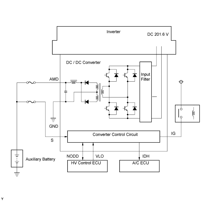
The DC / DC converter converts the DC 201.6 V of the HV battery into DC 12 V in order to supply power to the vehicle's lighting, audio and ECU systems. In addition, it charges the auxiliary battery.
A transistor bridge circuit initially converts DC 201.6 V into alternating current, and a transformer lowers its voltage. Then, it is rectified and smoothed (into DC) and converted into DC 12 V.
The DC / DC converter controls the output voltage in order to keep a constant voltage at the terminals of the auxiliary battery.

A125416E01

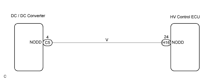
The HV control ECU uses the NODD signal line to transmit a stop command to the DC / DC converter and receive signals indicating the normal or abnormal conditions of the 12 V charging system.
If the vehicle is being driven with an inoperative DC / DC converter, the voltage of the auxiliary battery will drop, which will prevent the continued operation of the vehicle. Therefore, the HV control ECU monitors the operation of the DC / DC converter and alerts the driver if it detects a malfunction.

DTC No.
INF Code
DTC Detection Condition
Trouble Area
P0A09
265
Open or GND short in NODD signal circuit of DC / DC converter
  1. Wire harness or connector
  2. Inverter with converter assembly
P0A10
263
+B short in NODD signal circuit of DC / DC converter
  1. Wire harness or connector
  2. Inverter with converter assembly

WIRING DIAGRAM


A092298E01


INSPECTION PROCEDURE

1.CHECK HARNESS AND CONNECTOR (HYBRID VEHICLE CONTROL ECU - DC / DC CONVERTER)


    A065745E35
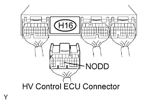
  1. Disconnect the H16 HV control ECU connector.


    A092030E01
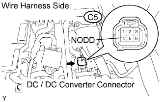
  1. Disconnect the C5 DC / DC converter connector.

  1. Turn the power switch ON (IG).

  1. Measure the voltage between the terminal of the HV control ECU connector and body ground.

    Standard voltage:
    Tester Connection
    Specified Condition
    NODD (H16-24) - Body ground
    Below 1 V

  1. Turn the power switch OFF.

  1. Measure the resistance between the wire harness side connectors.

    Standard resistance (Check for open):
    Tester Connection
    Specified Condition
    NODD (H16-24) - NODD (C5-4)
    Below 1 Ω
    Standard resistance (Check for short):
    Tester Connection
    Specified Condition
    NODD (H16-24) or NODD (C5-4) - Body ground
    10 kΩ or higher

  1. Reconnect the DC / DC converter connector.

  1. Reconnect the HV control ECU connector.


NG
REPAIR OR REPLACE HARNESS OR CONNECTOR
OK

REPLACE INVERTER WITH CONVERTER ASSEMBLY