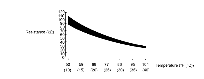
DTC P0A2C-247 Drive Motor "A" Temperature Sensor Circuit Low |
DTC P0A2D-249 Drive Motor "A" Temperature Sensor Circuit High |
| DTC No. | INF Code | DTC Detection Condition | Trouble Area |
| P0A2C | 247 | GND short in No. 1 motor temperature sensor circuit |
|
| P0A2D | 249 | Open or +B short in No. 1 motor temperature sensor circuit |
|
| Temperature Displayed | Malfunction |
| -58°F (50°C) | Open or +B short circuit |
| 401°F (205°C) | GND short circuit |
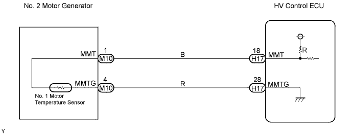
| 1.READ VALUE OF THE TECHSTREAM (MOTOR TEMP NO1) |
Connect the Techstream to the DLC3.
Turn the power switch ON (IG).
Enter the following menus: Powertrain / Engine Control / Data List.
Read the "Motor Temp No1" value.
| Temperature Displayed | Proceed to |
| -58°F (-50°C) | A |
| 401°F (205°C) | B |
| -57°F to 400°F (-49°C to 204°C) | C |
|
| ||||
|
| ||||
| A | |
 |
| 2.INSPECT HYBRID VEHICLE MOTOR ASSEMBLY (CHECK FOR OPEN OR +B SHORT) |
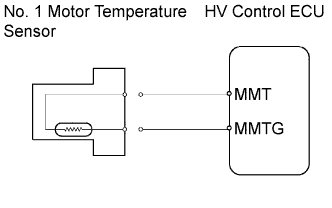 |
Disconnect the M10 No. 1 motor temperature sensor connector.
Turn the power switch ON (IG).
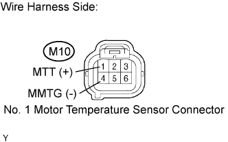 |
Measure the voltage between the terminals of the No. 1 motor temperature sensor connector.
| Tester Connection | Voltage | Proceed to |
| MMT (M10-1) - MMTG (M10-4) | Approximately 5 V | A |
| MMT (M10-1) - MMTG (M10-4) | 9 to 14 V | B |
| MMT (M10-1) - MMTG (M10-4) | Approximately 0 V | C |
Reconnect the No. 1 motor temperature sensor connector.
|
| ||||
|
| ||||
| B | |
|
| 3.CHECK HARNESS AND CONNECTOR (CHECK FOR +B SHORT) |
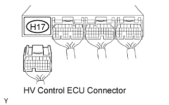 |
Disconnect the H17 HV control ECU connector.
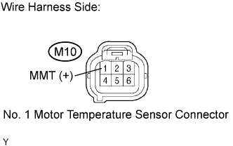 |
Disconnect the M10 No. 1 motor temperature sensor connector.
Turn the power switch ON (IG).
Measure the voltage between the terminal of the No. 1 motor temperature sensor connector and body ground.
| Tester Connection | Specified Condition |
| MMT (M10-1) - Body ground | Approximately 0 V |
Reconnect the HV control ECU connector.
Reconnect the No. 1 motor temperature sensor connector.
|
| ||||
| OK | ||
 | ||
| ||
| 4.READ VALUE OF THE TECHSTREAM (CHECK FOR OPEN IN HYBRID VEHICLE CONTROL ECU) |
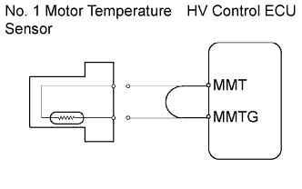 |
Disconnect the M10 No. 1 motor temperature sensor connector.
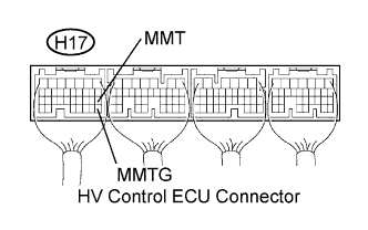 |
Connect terminals MMT and MMTG of the H17 HV control ECU connector.
Turn the power switch ON (IG).
Enter the following menus: Powertrain / Engine Control / Data List.
Read the "Motor Temp No1" value.
Reconnect the No. 1 motor temperature sensor connector.
|
| ||||
| OK | ||
| ||
| ||
| 5.READ VALUE OF THE TECHSTREAM (CHECK FOR GND SHORT IN WIRE HARNESS) |
|
Disconnect the M10 No. 1 motor temperature sensor connector.
Turn the power switch ON (IG).
Enter the following menus: Powertrain / Engine Control / Data List.
Read the "Motor Temp No1" value.
Reconnect the No. 1 motor temperature sensor connector.
|
| ||||
| NG | |
|
| 6.READ VALUE OF THE TECHSTREAM (CHECK FOR GND SHORT IN HYBRID VEHICLE CONTROL ECU) |
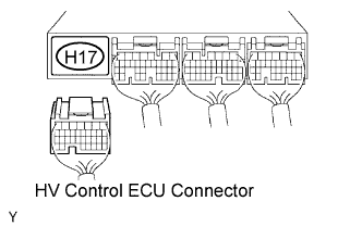 |
Disconnect the H17 HV control ECU connector.
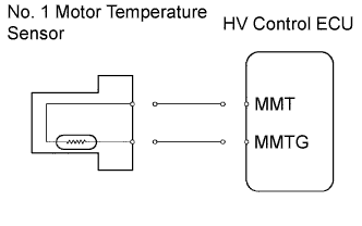 |
Turn the power switch ON (IG).
Enter the following menus: Powertrain / Engine Control / Data List.
Read the "Motor Temp No1" value.
Reconnect the HV control ECU connector.
|
| ||||
| OK | ||
| ||
| ||

