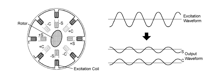
DTC P0A3F-243 Drive Motor "A" Position Sensor Circuit |
DTC P0A40-500 Drive Motor "A" Position Sensor Circuit Range / Performance |
DTC P0A41-245 Drive Motor "A" Position Sensor Circuit Low |
| DTC No. | INF Code | DTC Detection Condition | Trouble Area |
| P0A3F | 243 | Interphase short in motor resolver circuit |
|
| P0A40 | 500 | Motor resolver output is out of normal range |
|
| P0A41 | 245 | Open or short in motor resolver circuit |
|
| Related DTCs | P0A3F (INF 243): Drive motor "A" position sensor circuit malfunction / Short circuit between phases P0A40 (INF 500): Drive motor "A" position sensor circuit malfunction / Range check P0A41(INF 245): Drive motor "A" position sensor circuit malfunction / Circuit discontinuity or short circuit |
| Required sensor / components | Motor resolver |
| Frequency of operation | Continuous |
| Duration | TOYOTA's intellectual property |
| MIL operation | Immediately |
| Sequence of operation | None |
| The monitor will run whenever the following DTCs are not present | TOYOTA's intellectual property |
| No other condition | - |
| Motor resolver | Circuit malfunction (interphase shot, open or short), or abnormal output |
| Motor resolver | DTCs P0A3F (INF 243), P0A40 (INF 500) and P0A41 (INF 245) are not detected |
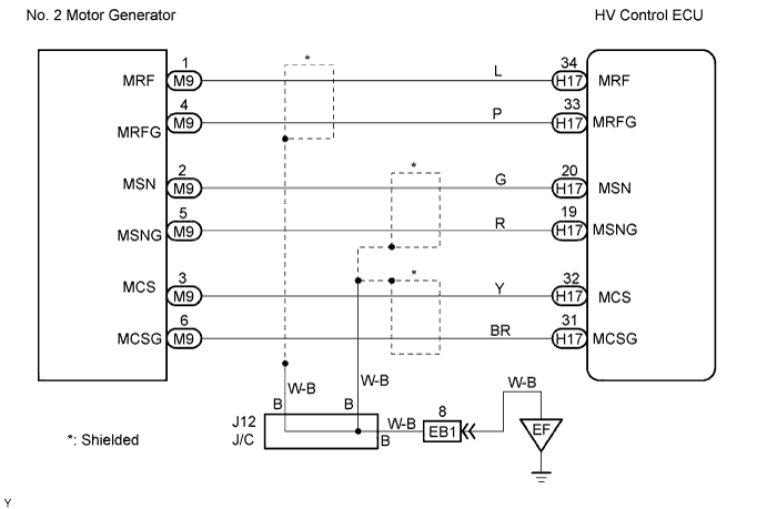
| 1.CHECK HARNESS AND CONNECTOR (HYBRID VEHICLE CONTROL ECU - MOTOR RESOLVER) |
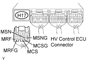 |
Disconnect the H17 HV control ECU connector.
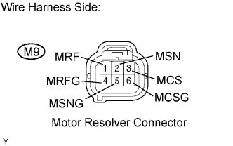 |
Disconnect the M9 motor resolver connector.
Turn the power switch ON (IG).
Measure the voltage between the terminals of the HV control ECU connector and body ground.
| Tester Connection | Specified Condition |
| MRF (H17-34) - Body ground | Below 1 V |
| MRFG (H17-33) - Body ground | Below 1 V |
| MSN (H17-20) - Body ground | Below 1 V |
| MSNG (H17-19) - Body ground | Below 1 V |
| MCS (H17-32) - Body ground | Below 1 V |
| MCSG (H17-31) - Body ground | Below 1 V |
Turn the power switch OFF.
Measure the resistance between the wire harness side connectors.
| Tester Connection | Specified Condition |
| MRF (H17-34) - MRF (M9-1) | Below 1 Ω |
| MRFG (H17-33) - MRFG (M9-4) | Below 1 Ω |
| MSN (H17-20) - MSN (M9-2) | Below 1 Ω |
| MSNG (H17-19) - MSNG (M9-5) | Below 1 Ω |
| MCS (H17-32) - MCS (M9-3) | Below 1 Ω |
| MCSG (H17-31) - MCSG (M9-6) | Below 1 Ω |
| Tester Connection | Specified Condition |
| MRF (H17-34) or MRF (M9-1) - Body ground | 10 kΩ or higher |
| MRFG (H17-33) or MRFG (M9-4) - Body ground | 10 kΩ or higher |
| MSN (H17-20) or MSN (M9-2) - Body ground | 10 kΩ or higher |
| MSNG (H17-19) or MSNG (M9-5) - Body ground | 10 kΩ or higher |
| MCS (H17-32) or MCS (M9-3) - Body ground | 10 kΩ or higher |
| MCSG (H17-31) or MCSG (M9-6) - Body ground | 10 kΩ or higher |
Reconnect the motor resolver connector.
Reconnect the HV control ECU connector.
|
| ||||
| OK | |
 |
| 2.INSPECT MOTOR RESOLVER |
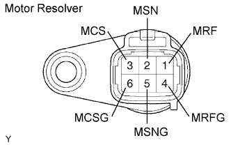 |
Disconnect the M9 motor resolver connector.
Measure the resistance between the terminals of the motor resolver.
| Tester Connection | Specified Condition |
| MRF (M9-1) - MRFG (M9-4) | 7.65 to 10.2 Ω |
| MSN (M9-2) - MSNG (M9-5) | 12.6 to 16.8 Ω |
| MCS (M9-3) - MCSG (M9-6) | 12.6 to 16.8 Ω |
Using a megohmmeter, measure the insulation resistance between the terminals of the motor resolver.
| Tester Connection | Specified Condition |
| MRF (M9-1) - MSN (M9-2) | 10 MΩ or higher |
| MRF (M9-1) - MCS (M9-3) | 10 MΩ or higher |
| MSN (M9-2) - MCS (M9-3) | 10 MΩ or higher |
| MRFG (M9-4) - MSNG (M9-5) | 10 MΩ or higher |
| MRFG (M9-4) - MCSG (M9-6) | 10 MΩ or higher |
| MSNG (M9-5) - MCSG (M9-6) | 10 MΩ or higher |
| Each terminal listed above - Transaxle housing | 10 MΩ or higher |
|
| ||||
| OK | ||
 | ||
| ||
