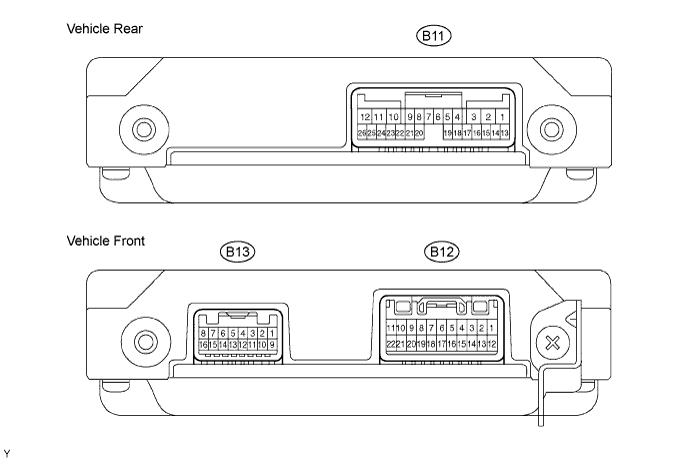
HYBRID BATTERY SYSTEM > TERMINALS OF ECU |
| CHECK BATTERY ECU |
Measure the voltage of the battery ECU connector.
| Symbols (Terminal No.) | Wiring Color | Terminal Description | Condition | Specified Condition |
| AM (B11-1) - GND (B11-12) | G - W-B | Auxiliary battery (for measuring battery voltage and for battery ECU memory) | Always | 9 to 14 V |
| IGCT (B11-2) - GND (B11-12) | L - W-B | Control signal | Power switch ON (READY) | 9 to 14 V |
| VM (B11-9) - GND (B11-12) | V - W-B | Battery blower motor monitoring signal | Battery blower motor mode 1 actuation (at low speed) | 10 to 14 V |
| VM (B11-9) - GND (B11-12) | V - W-B | Battery blower motor monitoring signal | Battery blower motor mode 6 actuation (at high speed) | 2 to 6 V |
| FCTL1 (B11-10) - GND (B11-12) | BR - W-B | No. 1 battery blower relay | Battery blower motor actuation | Below 1 V |
| IG2 (B11-13) - GND (B11-12) | O - W-B | IG signal | Power switch ON (IG) | 9 to 14 V |
| CANH (B11-18) - GND (B11-12) | B - W-B | HIGH-level CAN bus line | Power switch ON (IG) | Pulse generation (See waveform 1) |
| CANL (B11-19) - GND (B11-12) | W - W-B | LOW-level CAN bus line | Power switch ON (IG) | Pulse generation (See waveform 2) |
| SI (B11-24) - GND (B11-12) | Y - W-B | Battery blower motor actuation signal | Battery blower motor modes 1 to 6 actuation | Pulse generation (See waveform 3) |
| TB1 (B13-1) - GB1 (B13-2) | W - W | HV battery temperature sensor 1 | HV battery temperature: -40 to 90°C (-40 to 194°F) | 4.8 to 1.0 V |
| TB2 (B13-3) - GB2 (B13-4) | B - B | HV battery temperature sensor 2 | HV battery temperature: -40 to 90°C (-40 to 194°F) | 4.8 to 1.0 V |
| TB3 (B13-5) - GB3 (B13-6) | L - L | HV battery temperature sensor 3 | HV battery temperature: -40 to 90°C (-40 to 194°F) | 4.8 to 1.0 V |
| TC1 (B13-9) - GC1 (B13-10) | G - G | Intake air temperature sensor | Intake air temperature: -40 to 90°C (-40 to 194°F) | 4.8 to 1.0 V |
| VIB (B13-15) - GIB (B13-14) | - | Power source of battery current sensor (a specific voltage) | Power switch ON (IG) | 4.5 to 5.5 V |
| IB (B13-16) - GIB (B13-14) | - | Battery current sensor | Power switch ON (READY) | 0.5 to 4.5 V |
| GND (B11-12) - Body ground | W-B - Body ground | Ground | Always (resistance check) | Below 6 Ω |
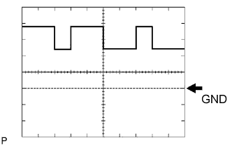 |
Using an oscilloscope, check the waveform 1.
| Item | Content |
| Symbols (Terminal No.) | CANH (B11-18) - GND (B11-12) |
| Tool Setting | 1 V/Div., 2 μsec./Div. |
| Condition | Power switch ON (IG) |
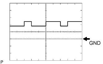 |
Using an oscilloscope, check the waveform 2.
| Item | Content |
| Symbols (Terminal No.) | CANL (B11-19) - GND (B11-12) |
| Tool Setting | 1 V/Div., 2 μsec./Div. |
| Condition | Power switch ON (IG) |
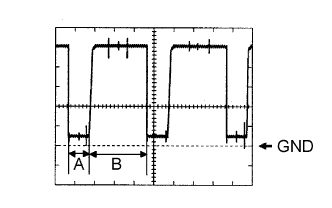 |
Using an oscilloscope, check the waveform 3.
| Item | Content |
| Symbols (Terminal No.) | SI (B11-24) - GND (B11-12) |
| Tool Setting | 1 V/Div., 50 μsec./Div. |
| Condition | During vehicle stop |
| Mode | A | B |
| 1 | 44.4 μsec. | 155.6 μsec. |
| 2 | 44.4 μsec. | 155.6 μsec. |
| 3 | 51.6 μsec. | 148.4 μsec. |
| 4 | 59.0 μsec. | 141.0 μsec. |
| 5 | 59.0 μsec. | 141.0 μsec. |
| 6 | 146.4 μsec. | 53.6 μsec. |