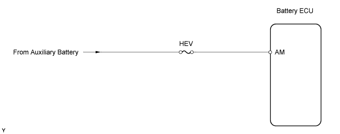
DTC P0560 System Voltage |
| DTC No. | DTC Detection Condition | Trouble Area |
| P0560 | Open in auxiliary battery power supply system while battery power is supplied to terminal IGCT (1 trip detection logic) |
|
| Related DTCs | P0560: Battery ECU/Range check |
| Required sensors/components | Main: Back-up power source circuit Sub: Battery ECU |
| Frequency of operation | Continuous |
| Duration | 1 second |
| MIL operation | Immediate after next power switch ON (IG) |
| Sequence of operation | None |
| The monitor will run whenever the following DTCs are not present | TOYOTA's intellectual property |
| Other conditions belong to TOYOTA's intellectual property | - |
| Stand-by RAM back-up voltage | 1 V or less |
| Auxiliary battery voltage | 9 to 14 V |
| 1.CHECK FUSE (HEV) |
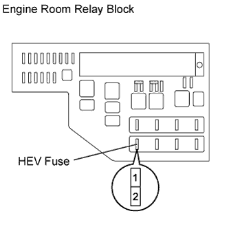 |
Remove the HEV fuse from the engine room relay block.
Measure the resistance of the HEV fuse.
Reinstall the HEV fuse.
|
| ||||
| OK | |
 |
| 2.CHECK WIRE HARNESS (BATTERY ECU - AUXILIARY BATTERY) |
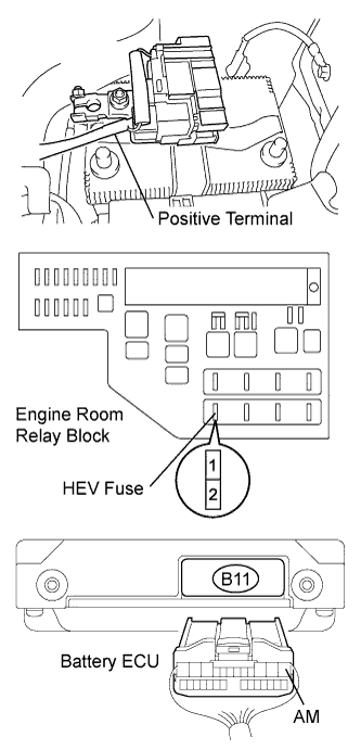 |
Disconnect the negative auxiliary battery terminal.
Disconnect the positive auxiliary battery terminal.
Remove the HEV fuse from the engine room relay block.
Disconnect the B11 battery ECU connector.
Measure the resistance of the wire harness side connectors.
| Tester Connection | Specified Condition |
| B11-1 (AM) - HEV fuse terminal 2 | Below 1 Ω |
| HEV fuse terminal 1 - Positive auxiliary battery terminal | Below 1 Ω |
Reconnect the battery ECU connector.
Reinstall the HEV fuse.
Reconnect the positive auxiliary battery terminal.
Reconnect the negative auxiliary battery terminal.
|
| ||||
| OK | ||
 | ||
| ||
| 3.CHECK WIRE HARNESS (BATTERY ECU - HEV FUSE) |
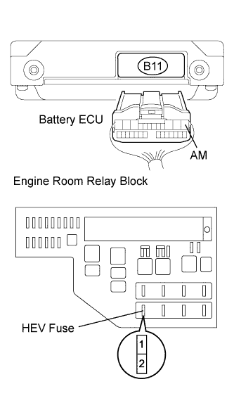 |
Disconnect the B11 battery ECU connector.
Remove the HEV fuse from the engine room relay block.
Measure the resistance of the wire harness side connector.
| Tester Connection | Specified Condition |
| B11-1 (AM) or HEV fuse terminal 2 - Body ground | 10 kΩ or higher |
Reconnect the battery ECU connector.
Reinstall the HEV fuse.
|
| ||||
| OK | ||
| ||
| ||

