| B |  |
| GO TO DTC CHART |
DTC P2601 Coolant Pump Control Circuit Range / Performance |
| DTC No. | DTC Detection Condition | Trouble Area |
| P2601 | Following conditions are successively met:
|
|
| Related DTCs | P2601: Coolant pump control circuit range/performance |
| Required sensors/components | Coolant heat storage tank outlet temperature sensor |
| Frequency of operation | Once per driving cycle |
| Duration | 10 seconds |
| MIL operation | 1 driving cycle |
| Sequence of operation | None |
| The monitor will run whenever the following DTCs are not present | None |
| Coolant heat storage system malfunction | Not detected |
| CHS water pump operation time | 3 seconds or more |
| Variation in CHS tank outlet temperature and engine coolant temperature before and after preheating | 2°C (3.6°F) or less |
| Storage coolant temperature | More than 65°C (149°F) |
| Difference in CHS tank outlet coolant temperature before and after CHS water pump ON | Less than 1°C (1.8°F) |
| 1.CHECK OTHER DTC OUTPUT (IN ADDITION TO DTC P2601) |
Connect Techstream to the DLC3.
Turn the power switch ON (IG).
Turn the tester ON.
Enter the following menus: Powertrain / Engine and ECT / Trouble Code.
Read the DTCs.
| Display (DTC Output) | Proceed to |
| P2601 | A |
| P2601 and other DTCs | B |
|
| ||||
| A | |
 |
| 2.PERFORM ACTIVE TEST BY TECHSTREAM (OPERATE WATER PUMP) |
Connect Techstream to the DLC3.
Turn the power switch ON (IG).
Turn the tester ON.
Enter the following menus: Powertrain / Engine and ECT / Active Test / Activate the Water Pump.
Check that the CHS W/P relay operates and the operating sounds of the water pump occurs.
| Tester operation | Specified Condition |
| WATER PUMP ON | CHS W/P relay and water pump operates |
|
| ||||
| OK | |
|
| 3.INSPECT TEMPERATURE SENSOR (CHS TANK OUTLET TEMPERATURE SENSOR) |
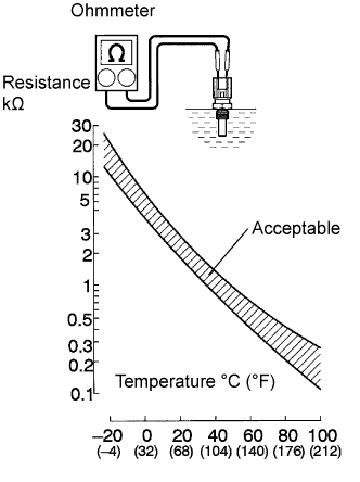 |
Remove the coolant heat storage (CHS) tank outlet temperature sensor.
Measure the resistance between the terminals.
| Tester Connection | Specified Condition |
| 1 - 2 | 2 to 3 kΩ at 20°C (68°F) |
| 1 - 2 | 0.2 to 0.4 kΩ at 80°C (176°F) |
Reinstall the coolant heat storage tank outlet temperature sensor.
|
| ||||
| OK | |
|
| 4.CHECK HARNESS AND CONNECTOR (ECM - CHS TANK OUTLET TEMPERATURE SENSOR) |
Check the harness and the connectors between the CHS tank outlet temperature sensor connector and the ECM connector.
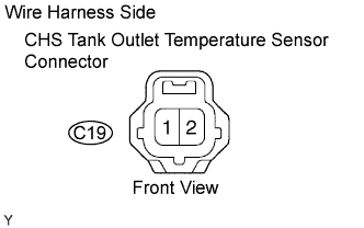 |
Disconnect the C19 CHS tank outlet temperature sensor connector.
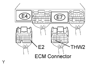 |
Disconnect the E4 and E7 ECM connectors.
Measure the resistance according to the value(s) in the table below.
| Tester Connection | Specified Condition |
| C19-2 (CHS tank outlet temperature sensor) - E7-33 (THW2) | Below 1 Ω |
| C19-1 (CHS tank outlet temperature sensor) - E4-28 (E2) | Below 1 Ω |
| Tester Connection | Specified Condition |
| C19-2 (CHS tank outlet temperature sensor) or E7-33 (THW2) - Body ground | 10 kΩ or higher |
Reconnect the CHS tank outlet temperature sensor connector.
Reconnect the ECM connectors.
|
| ||||
| OK | ||
 | ||
| ||
| 5.INSPECT COOLANT HEAT STORAGE WATER PUMP RELAY (CHS WATER PUMP RELAY) |
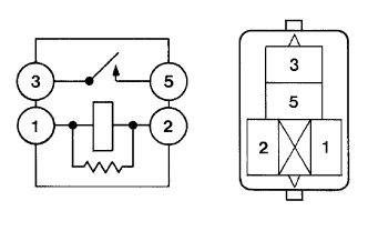 |
Remove the CHS W/P relay from the engine room relay block No. 2.
Inspect the CHS W/P relay.
| Tester Connection | Specified Condition |
| 3 - 5 | Below 1 Ω |
| 3 - 5 | 10 kΩ or higher (Apply battery voltage to terminals 1 and 2) |
Reinstall the CHS W/P relay.
|
| ||||
| OK | |
|
| 6.INSPECT WATER W/MOTOR & BRACKET PUMP ASSEMBLY |
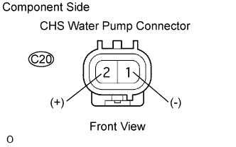 |
Disconnect the C20 CHS water pump connector.
Measure the resistance between the terminals of the water pump.
| Tester Connection | Specified Condition |
| 1 - 2 | 0.3 to 100 Ω |
Reconnect the CHS water pump connector.
|
| ||||
| OK | |
|
| 7.CHECK HARNESS AND CONNECTOR (CHS W/P RELAY - WATER PUMP AND ECM, WATER PUMP - GROUND) |
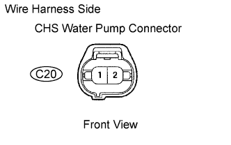 |
Check the harness and the connectors between the CHS water pump connector and the ECM connector.
Remove the CHS W/P relay from the engine room relay block No. 2.
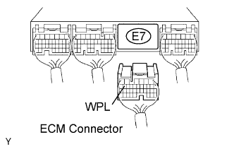 |
Disconnect the E7 ECM connector.
Measure the resistance according to the value(s) in the table below.
| Tester Connection | Specified Condition |
| E7-15 (WPL) - 2 (CHS W/P relay) | Below 1 Ω |
| Tester Connection | Specified Condition |
| 2 (CHS W/P relay) or E7-15 (WPL) - Body ground | 10 kΩ or higher |
Reinstall the integration relay.
Reconnect the ECM connector.
Check the harness and the connectors between the CHS water pump connector and the CHS W/P relay.
Disconnect the CHS water pump connector.
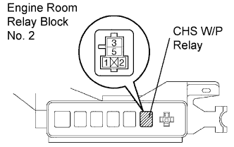 |
Remove the CHS W/P relay from the engine room relay block No. 2.
Measure the resistance according to the value(s) in the table below.
| Tester Connection | Specified Condition |
| 2 (CHS water pump) - 5 (CHS W/P relay) | Below 1 Ω |
| 1 (CHS water pump) - Body ground | Below 1 Ω |
| Tester Connection | Specified Condition |
| 2 (CHS water pump) or 5 (CHS W/P relay) - Body ground | 10 kΩ or higher |
Reconnect the CHS water pump connector.
Reinstall the integration relay.
|
| ||||
| OK | ||
| ||
| ||
