| YES |  |
| GO TO RELEVANT DTC CHART |
DTC P3004-132 Power Cable Malfunction |
| DTC No. | INF Code | DTC Detection Condition | Trouble Area |
| P3004 | 132 | Inverter voltage sensor malfunction, or limiter resistance increases |
|
| 1.READ OUTPUT DTC (HV ECU) |
Connect the Techstream to the DLC3.
Turn the power switch ON (IG).
Enter the following menus: Powertrain / Hybrid Control / Trouble Codes.
Check if DTCs are output.
|
| ||||
| NO | |
 |
| 2.INSPECT SYSTEM MAIN RESISTOR |
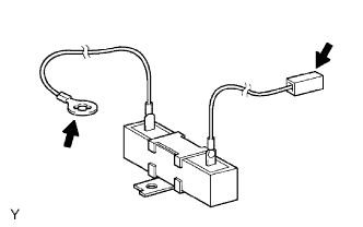 |
Remove the system main resistor .
Measure the resistance between the terminals.
Reinstall the system main resistor .
|
| ||||
| OK | |
|
| 3.INSPECT NO. 1 SYSTEM MAIN RELAY |
Inspect the No. 1 system main relay .
|
| ||||
| OK | |
|
| 4.INSPECT NO. 3 SYSTEM MAIN RELAY |
Inspect the No. 3 system main relay .
|
| ||||
| OK | |
|
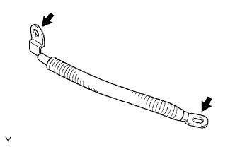
| 5.INSPECT MAIN BATTERY CABLE |
 |
Remove the HV battery assembly .
Remove the main battery cable .
Measure the resistance between the terminals of the main battery cable.
|
| ||||
| OK | |
|
| 6.INSPECT MAIN BATTERY CABLE |
Check the cover and terminals of the main battery cable for any abnormality.
Check the terminals of the HV battery and the system main relay, which are to be connected to the main cable, for any abnormality.
|
| ||||
| OK | |
|
| 7.INSPECT NO. 2 MAIN BATTERY CABLE |
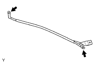 |
Remove the No. 2 main battery cable with the HV battery assembly removed .
Measure the resistance between the terminals of the No. 2 main battery cable.
|
| ||||
| OK | |
|
| 8.INSPECT NO. 2 MAIN BATTERY CABLE |
Check the cover and terminals of the No. 2 main battery cable for any abnormality.
Check the terminals of the HV battery and the system main relay, which are to be connected to the No. 2 main battery cable, for any abnormality.
|
| ||||
| OK | |
|
| 9.INSPECT FRAME WIRE |
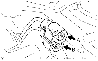 |
Disconnect the frame wire from the inverter with converter.
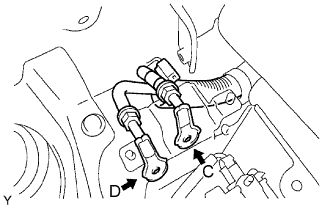 |
Check that the frame wire has been disconnected from the system main relay.
Using a megohmmeter, measure the insulation resistance between the high-voltage terminals of the frame wire and body ground.
| Tester Connection | Specified Condition |
| A - Body ground | 10 MΩ or higher |
| B - Body ground | 10 MΩ or higher |
Measure the resistance between the terminals of the frame wire.
| Tester Connection | Specified Condition |
| A - C | Below 1 Ω |
| B - D | Below 1 Ω |
Reinstall the HV battery assembly .
Reconnect the frame wire.
|
| ||||
| OK | |
|
| 10.CHECK HARNESS AND CONNECTOR (HYBRID VEHICLE CONTROL ECU - INVERTER) |
Turn the power switch OFF.
Remove the service plug grip .
Remove the inverter cover .
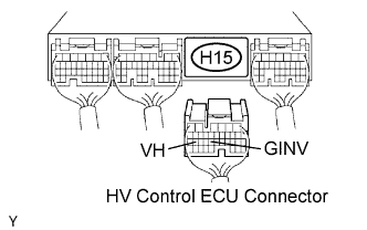 |
Disconnect the H15 HV control ECU connector.
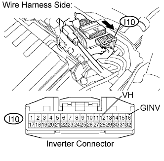 |
Disconnect the I10 inverter connector.
Turn the power switch ON (IG).
Measure the voltage between the terminals of the HV control ECU connector and body ground.
| Tester Connection | Specified Condition |
| VH (H15-26) - Body ground | Below 1 V |
| GINV (H15-23) - Body ground | Below 1 V |
Turn the power switch OFF.
Measure the resistance between the wire harness side connectors.
| Tester Connection | Specified Condition |
| VH (H15-26) or VH (I10-12) - Body ground | 10 kΩ or higher |
| GINV (H15-23) or GINV (I10-16) - Body ground | 10 kΩ or higher |
Reconnect the inverter connector.
Reconnect the HV control ECU connector.
Reinstall the inverter cover .
Reinstall the service plug grip .
|
| ||||
| OK | |
|
| 11.CHECK HYBRID VEHICLE CONTROL ECU (VH VOLTAGE) |
Turn the power switch ON (READY).
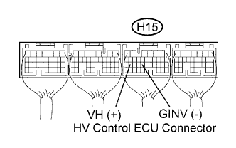 |
Measure the voltage between the terminals of the H15 HV control ECU connector.
| Tester Connection | Specified Condition |
| VH (H15-26) - GINV (H15-23) | 1.6 to 3.8 V |
|
| ||||
| OK | ||
 | ||
| ||