Home › HYBRID SYSTEM › P112 HYBRID VEHICLE CONTROL › HYBRID CONTROL SYSTEM

DTC    P0A94-558    DC / DC Converter Performance

DTC    P0A94-559    DC / DC Converter Performance

DTC    P0A94-560    DC / DC Converter Performance

for Preparation Click here


DESCRIPTION

See the description of the boost converter .
Upon receiving a boost converter gate shutdown signal from the HV control ECU, the boost converter forcefully stops the operation of the boost converter by turning OFF the power transistors that are actuating the boost converter.
The HV control ECU monitors the boost converter gate shutdown signal line and detects a malfunction.

DTC No.
INF Code
DTC Detection Condition
Trouble Area
P0A94
558
GND short in boost converter gate shutdown (CSDN) signal circuit
  1. Wire harness or connector
  2. Inverter with converter assembly
P0A94
559
Open or +B short in boost converter gate shutdown (CSDN) signal circuit
  1. Wire harness or connector
  2. Inverter with converter assembly
P0A94
560
Open in boost converter gate shutdown (CSDN) signal circuit
  1. Wire harness or connector
  2. Inverter with converter assembly

MONITOR DESCRIPTION

The HV control ECU monitors the boost converter gate shutdown (CSDN) signal line. If the HV control ECU detects an open or short malfunction of the CSDN signal circuit, the HV control ECU illuminates the MIL and sets a DTC.

MONITOR STRATEGY


Related DTCs
P0A94 (INF 558 / 559 / 560):
Boost converter / Converter gate shutdown signal malfunction
Required sensor / components
Boost converter
Frequency of operation
Continuous
Duration
TOYOTA's intellectual property
MIL operation
1 driving cycle
Sequence of operation
None

TYPICAL ENABLING CONDITIONS


The monitor will run whenever the following DTCs are not present
TOYOTA's intellectual property
Other conditions belong to TOYOTA's intellectual property
-

TYPICAL MALFUNCTION THRESHOLDS


Boost converter gate shutdown signal circuit
Open or short

COMPONENT OPERATING RANGE


Boost converter
DTC P0A94 (INF 558 / 559 / 560) is not detected

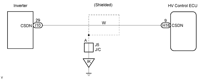
WIRING DIAGRAM


A092105E06


INSPECTION PROCEDURE

CAUTION:
  1. Before inspecting the high-voltage system, take safety precautions to prevent electrical shocks, such as wearing insulated gloves and removing the service plug grip. After removing the service plug grip, put it in your pocket to prevent other technicians from reconnecting it while you are servicing the high-voltage system.
  2. After disconnecting the service plug grip, wait for at least 5 minutes before touching any of the high-voltage connectors or terminals.

HINT:
At least 5 minutes are required to discharge the high-voltage condenser inside the inverter.

1.CHECK HARNESS AND CONNECTOR (HYBRID VEHICLE CONTROL ECU - INVERTER)

CAUTION:
Wear insulated gloves before performing the following operation.

  1. Turn the power switch OFF.

  1. Remove the service plug grip .

    NOTICE:
    Turning the power switch ON (READY) with the service plug grip removed could cause malfunction. Therefore, never turn the power switch ON (READY) in this state.


    A065745E38
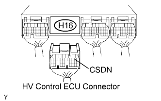
  1. Disconnect the H16 HV control ECU connector.

  1. Remove the inverter cover .


    A092041E46
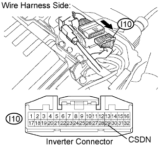
  1. Disconnect the I10 inverter connector.

  1. Turn the power switch ON (IG).

    HINT:
    DTCs for the interlock switch system are output when turning the power switch ON (IG) with both service plug grip and inverter cover removed.

  1. Measure the voltage between the terminal of the HV control ECU connector and body ground.

    Standard voltage:
    Tester Connection
    Specified Condition
    CSDN (H16-9) - Body ground
    Below 1 V

  1. Turn the power switch OFF.

  1. Measure the resistance between the wire harness side connectors.

    Standard resistance (Check for open):
    Tester Connection
    Specified Condition
    CSDN (H16-9) - CSDN (I10-29)
    Below 1 Ω
    Standard resistance (Check for short):
    Tester Connection
    Specified Condition
    CSDN (H16-9) or CSDN (I10-29) - Body ground
    10 kΩ or higher

  1. Reconnect the inverter connector.

  1. Reconnect the HV control ECU connector.

  1. Reinstall the inverter cover .

  1. Reinstall the service plug grip .


NG
REPAIR OR REPLACE HARNESS OR CONNECTOR
OK

REPLACE INVERTER WITH CONVERTER ASSEMBLY