| YES |  |
| GO TO RELEVANT DTC CHART |
DTC P0A94-585 DC / DC Converter Performance |
| DTC No. | INF Code | DTC Detection Condition | Trouble Area |
| P0A94 | 585 | Boost converter voltage (VL) sensor performance problem |
|
| Related DTCs | P0A94 (INF 585): Boost converter / Voltage (VL) sensor deviation |
| Required sensor / components | Boost converter, inverter, battery ECU |
| Frequency of operation | Continuous |
| Duration | TOYOTA's intellectual property |
| MIL operation | Immediately |
| Sequence of operation | None |
| The monitor will run whenever the following DTCs are not present | TOYOTA's intellectual property |
| Other conditions belong to TOYOTA's intellectual property | - |
| TOYOTA's intellectual property | - |
| Boost converter | DTC P0A94 (INF 585) is not detected |
| 1.READ OUTPUT DTC (HV ECU) |
Connect the Techstream to the DLC3.
Turn the power switch ON (IG).
Enter the following menus: Powertrain / Hybrid Control / Trouble Codes.
Check if DTCs are output.
|
| ||||
| NO | |
 |
| 2.CHECK HARNESS AND CONNECTOR (HYBRID VEHICLE CONTROL ECU - INVERTER) |
Turn the power switch OFF.
Remove the service plug grip .
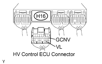 |
Disconnect the H16 HV control ECU connector.
Remove the inverter cover .
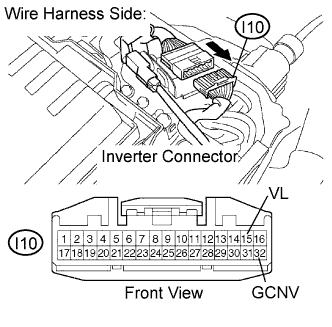 |
Disconnect the I10 inverter connector.
Turn the power switch ON (IG).
Measure the voltage between the terminals of the HV control ECU connector and body ground.
| Tester Connection | Specified Condition |
| VL (H16-30) - Body ground | Below 1 V |
| GCNV (H16-8) - Body ground | Below 1 V |
Turn the power switch OFF.
Measure the resistance between the wire harness side connectors.
| Tester Connection | Specified Condition |
| VL (H16-30) - VL (I10-15) | Below 1 Ω |
| GCNV (H16-8) - GCNV (I10-32) | Below 1 Ω |
| Tester Connection | Specified Condition |
| VL (H16-30) or VL (I10-15) - Body ground | 10 kΩ or higher |
| GCNV (H16-8) or GCNV (I10-32) - Body ground | 10 kΩ or higher |
Reconnect the inverter connector.
Reconnect the HV control ECU connector.
Reinstall the inverter cover .
Reinstall the service plug grip .
|
| ||||
| OK | ||
 | ||
| ||