Home › HYBRID SYSTEM › P112 HYBRID VEHICLE CONTROL › HYBRID CONTROL SYSTEM

DTC    U0100-211    Lost Communication with ECM / PCM "A"

DTC    U0100-212    Lost Communication with ECM / PCM "A"

DTC    U0100-530    Lost Communication with ECM / PCM "A"

DTC    U0111-208    Lost Communication with Battery Energy Control Module "A"

DTC    U0111-531    Lost Communication with Battery Energy Control Module "A"

DTC    U0129-220    Lost Communication with Brake System Control Module

DTC    U0129-222    Lost Communication with Brake System Control Module

DTC    U0129-528    Lost Communication with Brake System Control Module

DTC    U0129-529    Lost Communication with Brake System Control Module

DTC    U0131-433    Lost Communication with Power Steering Control Module

DTC    U0131-434    Lost Communication with Power Steering Control Module

DTC    U0146-435    Lost Communication with Gateway "A"

for Preparation Click here


DESCRIPTION

The HV control ECU transmits and receives signals to and from the ECM, battery ECU, skid control ECU, power steering ECU, and the gateway ECU via CAN (Controller Area Network) communication.

DTC No.
INF Code
DTC Detection Condition
Trouble Area
U0100
211
CAN communication problem between ECM and HV control ECU (no signal input)
  1. CAN communication system
U0100
212
CAN communication problem between ECM and HV control ECU (transmission error)
  1. CAN communication system
U0100
530
CAN communication problem between ECM and HV control ECU (CAN communication system malfunction)
  1. CAN communication system
U0111
208
CAN communication problem between battery ECU and HV control ECU (no signal input)
  1. CAN communication system
U0111
531
CAN communication problem between battery ECU and HV control ECU (CAN communication system malfunction)
  1. CAN communication system
U0129
220
CAN communication problem between skid control ECU and HV control ECU (no signal input)
  1. CAN communication system
U0129
222
CAN communication problem between skid control ECU and HV control ECU (CAN communication system malfunction)
  1. CAN communication system
U0129
528
CAN communication problem between skid control ECU and HV control ECU (transmission error)
  1. CAN communication system
U0129
529
CAN communication problem between skid control ECU and HV control ECU (regenerative torque malfunction)
  1. CAN communication system
U0131
433
CAN communication problem between power steering ECU and HV control ECU (no signal input)
  1. CAN communication system
U0131
434
CAN communication problem between power steering ECU and HV control ECU (CAN communication system malfunction)
  1. CAN communication system
U0146
435
CAN communication problem between gateway ECU and HV control ECU (no signal input)
  1. CAN communication system

MONITOR DESCRIPTION

If the HV control ECU detects a malfunction in the CAN communication with the ECM or battery ECU, it illuminates the MIL and sets a DTC.

MONITOR STRATEGY


U0100: 
Related DTCs
U0100 (INF 211):
Receiving check for the specific frame
U0100 (INF 212):
Sending data check
U0100 (INF 530):
Receiving check for the all frame
Required sensor / components
Main: ECM
Sub: CAN bus line
Frequency of operation
Continuous
Duration
U0100 (INF 211, 212): 0.1 second or more
U0100 (INF 530): 1.91 seconds or more
MIL operation
1 driving cycle
Sequence of operation
None

U0111: 
Related DTCs
U0111 (INF 208):
Receiving check for the specific frame
U0111 (INF 531):
Receiving check for the all frame
Required sensor / components
Main: Battery ECU
Sub: CAN bus line
Frequency of operation
Continuous
Duration
U0111 (INF 208): 0.1 second or more
U0111 (INF 531): 1.6 seconds or more
MIL operation
1 driving cycle
Sequence of operation
None

TYPICAL ENABLING CONDITIONS


The monitor will run whenever the following DTCs are not present
TOYOTA's intellectual property
Other conditions belong to TOYOTA's intellectual property
-

TYPICAL MALFUNCTION THRESHOLDS


CAN communication
Communication failure

COMPONENT OPERATING RANGE


ECM
DTC U0100 (INF 211 / 212 / 530) is not detected
Battery ECU
DTC U0111 (INF 208 / 531) is not detected

INSPECTION PROCEDURE

1.READ OUTPUT DTC (CODES ALL)
  1. Connect the Techstream to the DLC3.

  1. Turn the power switch ON (IG).

  1. Enter the following menus: Utility / All Codes.

  1. Read and record CAN communication malfunction DTCs.

    Result:

    Display (DTC Output)
    Proceed to
    U0100 (INF 211) or U0129 (INF 220)
    A
    U0100 (INF 211) and CAN communication malfunction DTCs
    B
    U0129 (INF 220) and CAN communication malfunction DTCs
    B
    P3108 (INF 594) and CAN communication malfunction DTCs
    B

    HINT:
    1. When DTCs other than CAN communication malfunction DTCs are output simultaneously, first correct the CAN communication problem, and then perform troubleshooting for other DTCs.
    2. DTC P3108 (INF 594) is one of the DTCs that indicates a CAN communication malfunction.


B
GO TO CAN COMMUNICATION SYSTEM
A


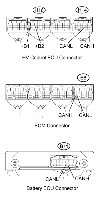
2.CHECK TERMINAL OF ECM AND ECUS (+B1, +B2, CANH AND CANL TERMINALS)


    A126988E01
  1. Check connection condition of each connector of the HV control ECU, ECM and battery ECU, as well as contact condition of each terminal shown in the table.
    Type of ECU
    Terminal No.
    Symbols
    HV control ECU
    H16-7
    +B1
    HV control ECU
    H16-6
    +B2
    HV control ECU
    H14-8
    CANH
    HV control ECU
    H14-9
    CANL
    ECM
    E6-31
    CANH
    ECM
    E6-30
    CANL
    Battery ECU
    B11-18
    CANH
    Battery ECU
    B11-19
    CANL

    OK:
    Connectors have been connected securely and there is no poor contact on each terminal.


NG
CONNECT SECURELY
OK

CHECK FOR INTERMITTENT PROBLEMS