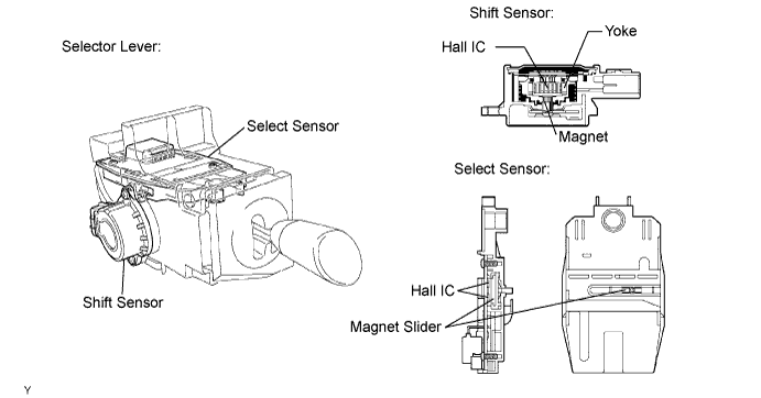
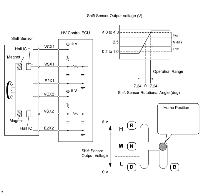
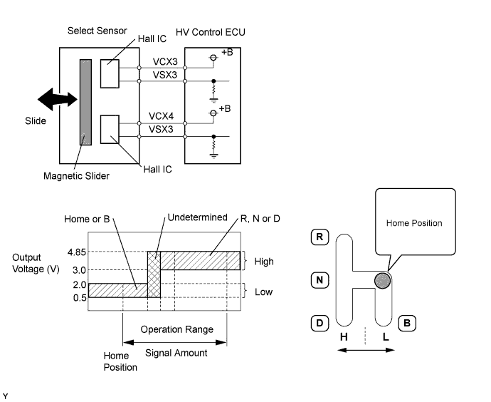
The HV control ECU determines the position of the selector lever in accordance with the combination of the signals from the shift sensor and select sensor.
DTC P0705-571 Transmission Range Sensor Circuit |
DTC P0705-572 Transmission Range Sensor Circuit |
DTC P0705-573 Transmission Range Sensor Circuit |
DTC P0705-574 Transmission Range Sensor Circuit |
DTC P0705-575 Transmission Range Sensor Circuit |
DTC P0705-576 Transmission Range Sensor Circuit |
DTC P0705-577 Transmission Range Sensor Circuit |
DTC P0705-578 Transmission Range Sensor Circuit |
DTC P0705-595 Transmission Range Sensor Circuit |
DTC P0705-596 Transmission Range Sensor Circuit |
| DTC No. | INF Code | DTC Detection Condition | Trouble Area |
| P0705 | 571 | Open or GND short in shift main sensor circuit |
|
| P0705 | 572 | +B short in shift main sensor circuit |
|
| P0705 | 573 | Open or GND short in shift sub sensor circuit |
|
| P0705 | 574 | +B short in shift sub sensor circuit |
|
| P0705 | 575 | Open or GND short in select main sensor circuit |
|
| P0705 | 576 | +B short in select main sensor circuit |
|
| P0705 | 577 | Open or GND short in select sub sensor circuit |
|
| P0705 | 578 | +B short in select sub sensor circuit |
|
| P0705 | 595 | Difference between shift main sensor value and shift sub sensor value is large |
|
| P0705 | 596 | Difference between select main sensor value and select sub sensor value is large |
|
| R Position (Main) | Home or N Position (Main) | D or B Position (Main) | R Position (Sub) | Home or N Position (Sub) | D or B Position (Sub) | Trouble Area |
| 0 to 0.2 V | 0 to 0.2 V | 0 to 0.2 V | 4.0 to 4.8 V | 2.0 to 3.0 V | 0.2 to 1.0 V | Open in VCX1 circuit |
| 4.0 to 4.8 V | 2.0 to 3.0 V | 0.2 to 1.0 V | 0 to 0.2 V | 0 to 0.2 V | 0 to 0.2 V | Open in VCX2 circuit |
| 0 to 0.2 V | 0 to 0.2 V | 0 to 0.2 V | 4.0 to 4.8 V | 2.0 to 3.0 V | 0.2 to 1.0 V | Open or short in VSX1 circuit |
| 4.0 to 4.8 V | 2.0 to 3.0 V | 0.2 to 1.0 V | 0 to 0.2 V | 0 to 0.2 V | 0 to 0.2 V | Open or short in VSX2 circuit |
| 4.8 to 5.0 V | 4.8 to 5.0 V | 4.8 to 5.0 V | 4.0 to 4.8 V | 2.0 to 3.0 V | 0.2 to 1.0 V | Open in E2X1 circuit |
| 4.0 to 4.8 V | 2.0 to 3.0 V | 0.2 to 1.0 V | 4.8 to 5.0 V | 4.8 to 5.0 V | 4.8 to 5.0 V | Open in E2X2 circuit |
| R, N or D Position (Select Main) | Home or B Position (Select Main) | R, N or D Position (Select Sub) | Home or B Position (Select Sub) | Trouble Area |
| 0 to 0.5 V | 0 to 0.5 V | 3.0 to 4.85 V | 0.5 to 2.0 V | Open or GND short in VCX3 or VSX3 circuit |
| 3.0 to 4.85 V | 0.5 to 2.0 V | 0 to 0.5 V | 0 to 0.5 V | Open or GND short in VCX4 or VSX4 circuit |
| 1.READ VALUE OF THE TECHSTREAM (SHIFT SENSOR MAIN AND SHIFT SENSOR SUB) |
Connect the Techstream to the DLC3.
Turn the power switch ON (IG).
Enter the following menus: Powertrain / Engine Control / Data List.
Read the "Shift Sensor Main" and "Shift Sensor Sub" voltage values.
| Shift Position | M Shift Sensor | S Shift Sensor |
| R position | 4.0 to 4.8 V | 4.0 to 4.8 V |
| Home or N position | 2.0 to 3.0 V | 2.0 to 3.0 V |
| D or B position | 0.2 to 1.0 V | 0.2 to 1.0 V |
|
| ||||
| NG | |
 |
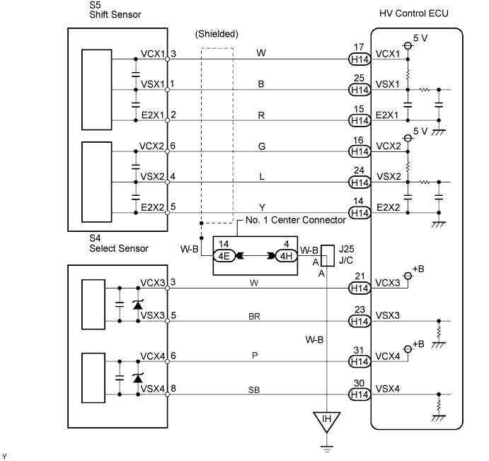
| 2.CHECK HARNESS AND CONNECTOR (HYBRID VEHICLE CONTROL ECU - SHIFT SENSOR) |
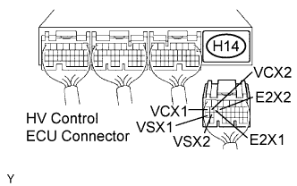 |
Disconnect the H14 HV control ECU connector.
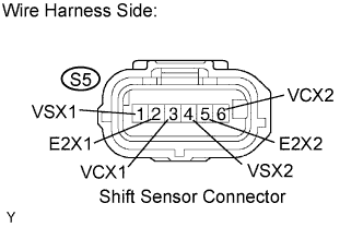 |
Disconnect the S5 shift sensor connector.
Turn the power switch ON (IG).
Measure the voltage between the terminals of the HV control ECU connector and body ground.
| Tester Connection | Specified Condition |
| VCX1 (H14-17) - Body ground | Below 1 V |
| VSX1 (H14-25) - Body ground | Below 1 V |
| E2X1 (H14-15) - Body ground | Below 1 V |
| VCX2 (H14-16) - Body ground | Below 1 V |
| VSX2 (H14-24) - Body ground | Below 1 V |
| E2X2 (H14-14) - Body ground | Below 1 V |
Turn the power switch OFF.
Measure the resistance between the wire harness side connectors.
| Tester Connection | Specified Condition |
| VCX1 (H14-17) - VCX1 (S5-3) | Below 1 Ω |
| VSX1 (H14-25) - VSX1 (S5-1) | Below 1 Ω |
| E2X1 (H14-15) - E2X1 (S5-2) | Below 1 Ω |
| VCX2 (H14-16) - VCX2 (S5-6) | Below 1 Ω |
| VSX2 (H14-24) - VSX2 (S5-4) | Below 1 Ω |
| E2X2 (H14-14) - E2X2 (S5-5) | Below 1 Ω |
| Tester Connection | Specified Condition |
| VCX1 (H14-17) or VCX1 (S5-3) - Body ground | 10 kΩ or higher |
| VSX1 (H14-25) or VSX1 (S5-1) - Body ground | 10 kΩ or higher |
| E2X1 (H14-15) or E2X1 (S5-2) - Body ground | 10 kΩ or higher |
| VCX2 (H14-16) or VCX2 (S5-6) - Body ground | 10 kΩ or higher |
| VSX2 (H14-24) or VSX2 (S5-4) - Body ground | 10 kΩ or higher |
| E2X2 (H14-14) or E2X2 (S5-5) - Body ground | 10 kΩ or higher |
Reconnect the shift sensor connector.
Reconnect the HV control ECU connector.
|
| ||||
| OK | |
|
| 3.CHECK HYBRID VEHICLE CONTROL ECU (VCX1 AND VCX2 VOLTAGE) |
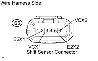 |
Disconnect the S5 shift sensor connector.
Turn the power switch ON (IG).
Measure the voltage between the terminals of the shift sensor connector.
| Tester Connection | Specified Condition |
| VCX1 (S5-3) - E2X1 (S5-2) | 4.5 to 5.5 V |
| VCX2 (S5-6) - E2X2 (S5-5) | 4.5 to 5.5 V |
Reconnect the shift sensor connector.
|
| ||||
| NG | ||
 | ||
| ||
| 4.READ VALUE OF THE TECHSTREAM (SHIFT SENSOR SELECT MAIN AND SHIFT SENSOR SELECT SUB) |
Connect the Techstream to the DLC3.
Turn the power switch ON (IG).
Enter the following menus: Powertrain / Engine Control / Data List.
Read the "Shift Sensor Select Main" and "Shift Sensor Select Sub" voltage values.
| Shift Position | Shift Sensor Select Main | Shift Sensor Select Sub |
| R, N or D position | 3.0 to 4.85 V | 3.0 to 4.85 V |
| Home or B position | 0.5 to 2.0 V | 0.5 to 2.0 V |
|
| ||||
| NG | |
|
| 5.CHECK HARNESS AND CONNECTOR (HYBRID VEHICLE CONTROL ECU - SELECT SENSOR) |
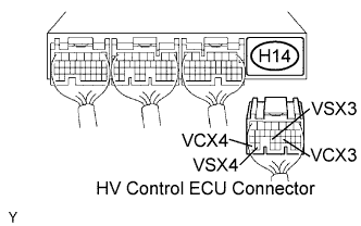 |
Disconnect the H14 HV control ECU connector.
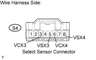 |
Disconnect the S4 select sensor connector.
Turn the power switch ON (IG).
Measure the voltage between the terminals of the HV control ECU connector and body ground.
| Tester Connection | Specified Condition |
| VCX3 (H14-21) - Body ground | Below 1 V |
| VSX3 (H14-23) - Body ground | Below 1 V |
| VCX4 (H14-31) - Body ground | Below 1 V |
| VSX4 (H14-30) - Body ground | Below 1 V |
Turn the power switch OFF.
Measure the resistance between the wire harness side connectors.
| Tester Connection | Specified Condition |
| VCX3 (H14-21) - VCX3 (S4-3) | Below 1 Ω |
| VSX3 (H14-23) - VSX3 (S4-5) | Below 1 Ω |
| VCX4 (H14-31) - VCX4 (S4-6) | Below 1 Ω |
| VSX4 (H14-30) - VSX4 (S4-8) | Below 1 Ω |
| Tester Connection | Specified Condition |
| VCX3 (H14-21) or VCX3 (S4-3) - Body ground | 10 kΩ or higher |
| VSX3 (H14-23) or VSX3 (S4-5) - Body ground | 10 kΩ or higher |
| VCX4 (H14-31) or VCX4 (S4-6) - Body ground | 10 kΩ or higher |
| VSX4 (H14-30) or VSX4 (S4-8) - Body ground | 10 kΩ or higher |
Reconnect the select sensor connector.
Reconnect the HV control ECU connector.
|
| ||||
| OK | |
|
| 6.INSPECT HYBRID VEHICLE CONTROL ECU (VCX3 AND VCX4 VOLTAGE) |
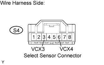 |
Disconnect the S4 select sensor connector.
Turn the power switch ON (IG).
Measure the voltage between the terminals of the select sensor connector and body ground.
| Tester Connection | Specified Condition |
| VCX3 (S4-3) - Body ground | 9 to 14 V |
| VCX4 (S4-6) - Body ground | 9 to 14 V |
Reconnect the select sensor connector.
|
| ||||
| OK | |
|
| 7.REPLACE SELECTOR LEVER |
| NEXT | |
|
| 8.READ OUTPUT DTC (DTC P0705 IS NOT OUTPUT AGAIN) |
Connect the Techstream to the DLC3.
Turn the power switch ON (IG).
Enter the following menus: Powertrain / Hybrid Control / Trouble Codes. (b) Clear DTCs and freeze frame data.
Perform a simulation test.
Enter the following menus: Powertrain / Hybrid Control / Trouble Codes.
Check if DTCs are output.
|
| ||||
| NO | ||
| ||
| ||

