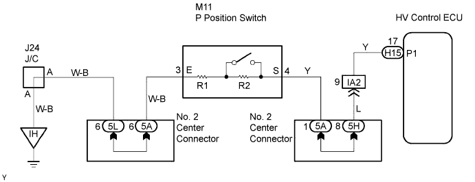
DTC P0851-579 Park / Neutral Switch Input Circuit Low |
DTC P0852-580 Park / Neutral Switch Input Circuit High |
| DTC No. | INF Code | DTC Detection Condition | Trouble Area |
| P0851 | 579 | GND short in P position switch circuit |
|
| P0852 | 580 | Open or +B short in P position switch circuit |
|
| 1.INSPECT P POSITION SWITCH |
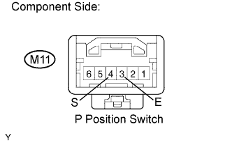 |
Remove the P position switch.
Measure the resistance between the terminals of the P position switch connector.
| Tester Connection | Condition | Specified Condition |
| S (M11-4) - E (M11-3) | Keep switch pressed | 680 Ω |
| S (M11-4) - E (M11-3) | Release switch | 4,580 Ω |
Reinstall the P position switch.
|
| ||||
| OK | |
 |
| 2.CHECK HARNESS AND CONNECTOR (HYBRID VEHICLE CONTROL ECU - P POSITION SWITCH) |
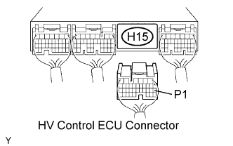 |
Disconnect the H15 HV control ECU connector.
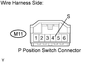 |
Disconnect the M11 P position switch connector.
Turn the power switch ON (IG).
Measure the voltage between the terminal of the HV control ECU connector and body ground.
| Tester Connection | Specified Condition |
| P1 (H15-17) - Body ground | Below 1 V |
Turn the power switch OFF.
Measure the resistance between the wire harness side connectors.
| Tester Connection | Specified Condition |
| P1 (H15-17) - S (M11-4) | Below 1 Ω |
| Tester Connection | Specified Condition |
| P1 (H15-17) or S (M11-4) - Body ground | 10 kΩ or higher |
Reconnect the P position switch connector.
Reconnect the HV control ECU connector.
|
| ||||
| OK | |
|
| 3.CHECK HARNESS AND CONNECTOR (P POSITION SWITCH - BODY GROUND) |
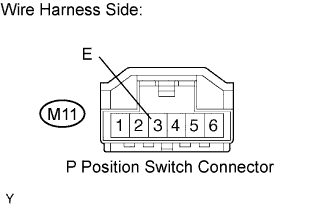 |
Disconnect the M11 P position switch connector.
Measure the resistance between the terminal of the P position switch connector and body ground.
| Tester Connection | Specified Condition |
| E (M11-3) - Body ground | Below 1 Ω |
Reconnect the P position switch connector.
|
| ||||
| OK | ||
 | ||
| ||
