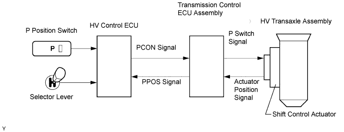
DTC P3102-524 Transmission Control ECU Malfunction |
DTC P3102-525 Transmission Control ECU Malfunction |
DTC P3102-581 Transmission Control ECU Malfunction |
DTC P3102-582 Transmission Control ECU Malfunction |
DTC P3102-597 Transmission Control ECU Malfunction |
DTC P3102-598 Transmission Control ECU Malfunction |
DTC P3102-599 Transmission Control ECU Malfunction |
| DTC No. | INF Code | DTC Detection Condition | Trouble Area |
| P3102 | 524 | BEAN communication problem of transmission control ECU assembly |
|
| P3102 | 525 | Transmission control ECU IG OFF command malfunction |
|
| P3102 | 581 | Transmission control ECU malfunction |
|
| P3102 | 582 | P position (PPOS) signal is logically inconsistent |
|
| P3102 | 597 | GND short in P position (PPOS) signal circuit |
|
| P3102 | 598 | +B short in P position (PPOS) signal circuit |
|
| P3102 | 599 | P position (PPOS) signal malfunction (output pulse is abnormal) |
|
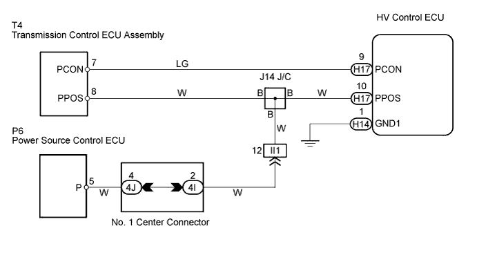
| 1.CHECK HARNESS AND CONNECTOR (HYBRID VEHICLE CONTROL ECU - TRANSMISSION CONTROL ECU ASSEMBLY AND POWER SOURCE CONTROL ECU) |
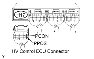 |
Disconnect the H17 HV control ECU connector.
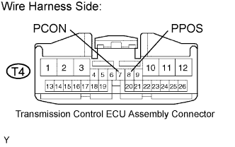 |
Disconnect the T4 transmission control ECU assembly connector.
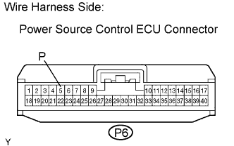 |
Disconnect the P6 power source control ECU connector.
Measure the voltage between the terminals of the HV control ECU connector and body ground.
| Tester Connection | Specified Condition |
| PCON (H17-9) - Body ground | Below 1 V |
| PPOS (H17-10) - Body ground | Below 1 V |
Measure the resistance between the wire harness side connectors.
| Tester Connection | Specified Condition |
| PCON (H17-9) - PCON (T4-7) | Below 1 Ω |
| PPOS (H17-10) - PPOS (T4-8) | Below 1 Ω |
| PPOS (H17-10) - P (P6-5) | Below 1 Ω |
| Tester Connection | Specified Condition |
| PCON (H17-9) or PCON (T4-7) - Body ground | 10 kΩ or higher |
| PPOS (H17-10) or PPOS (T4-8) - Body ground | 10 kΩ or higher |
| PPOS (H17-10) or P (P6-5) - Body ground | 10 kΩ or higher |
Reconnect the power source control ECU connector.
Reconnect the transmission control ECU assembly connector.
Reconnect the HV control ECU connector.
|
| ||||
| OK | |
 |
| 2.CHECK HARNESS AND CONNECTOR (CHECK FOR +B SHORT IN WIRE HARNESS) |
 |
Inspect the HV control ECU using an oscilloscope.
Turn the power switch ON (IG).
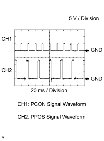 |
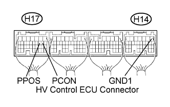
Check the waveforms of the voltages between the terminals PCON (H17-9) and GND1 (H14-1), and terminals PPOS (H17-10) and GND1 (H14-1), of the HV control ECU connectors, in order to check for +B short in the signal lines PCON and PPOS.
|
| ||||
| OK | |
|
| 3.READ OUTPUT DTC (TRANSMISSION CONTROL) |
Connect the Techstream to the DLC3.
Turn the power switch ON (IG).
Enter the following menus: Chassis / Transmission Control / Trouble Codes.
Check if DTCs are output.
|
| ||||
| NO | ||
 | ||
| ||
