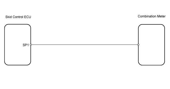
METER / GAUGE SYSTEM > Speedometer Malfunction |
| 1.READ VALUE OF TECHSTREAM (FR/FL/RR/RL WHEEL SPEED) |
Check the Data List for proper functioning of the vehicle speed signal.
| Item | Measurement Item / Range (Display) | Normal Condition | Diagnostic Note |
| (FR/FL/RR/RL) Wheel Speed | Vehicle speed / Min.: 0 km/h (0 mph), Max.: 326 km/h (202 mph) | Almost same as actual speed (When driving) | - |
|
| ||||
| OK | |
 |
| 2.CHECK COMBINATION METER ASSEMBLY |
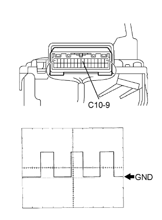 |
Using an oscilloscope, check the signal waveform of the meter.
| Tester Connection | Tool Setting | Vehicle Condition |
| C10-9 - Body ground | 5 V/DIV., 20 msec./DIV. | Driving at approx. 20 km/h (12 mph) |
|
| ||||
| NG | |
|
| 3.CHECK WIRE HARNESS (ECU - METER) |
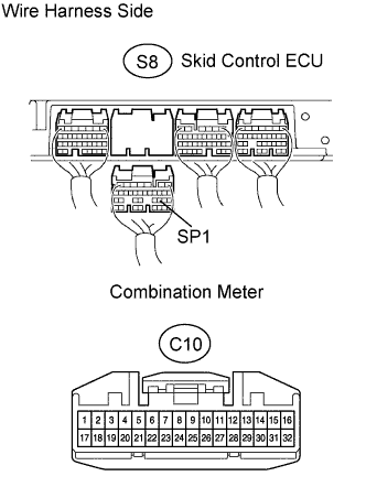 |
Disconnect the S8 ECU connector.
Disconnect the C10 meter connector.
Measure the resistance of the wire harness side connectors.
| Tester Connection | Specified Condition |
| C10-9 - S8-22 (SP1) | Below 1 Ω |
| C10-9 - Body ground | 10 kΩ or higher |
|
| ||||
| OK | ||
 | ||
| ||
