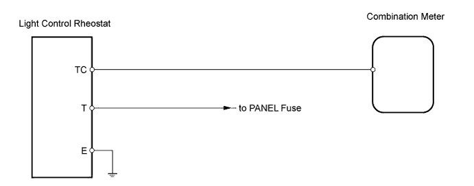
METER / GAUGE SYSTEM > Operating Light Control Rheostat does not Change Light Brightness |
| 1.INSPECT LIGHT CONTROL RHEOSTAT |
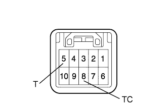 |
Remove the light control rheostat.
Measure the resistance of the rheostat.
| Tester Connection | Condition | Specified Condition |
| 5 (T) - 8 (TC) | Not in tail cancel position | Below 1 Ω |
| Tail cancel position (rheostat knob is fully turned up) | 10 kΩ or higher |
|
| ||||
| OK | |
 |
| 2.CHECK WIRE HARNESS (RHEOSTAT - METER, BATTERY AND BODY GROUND) |
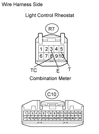 |
Disconnect the R7 rheostat connector.
Disconnect the C10 meter connector.
Measure the resistance of the wire harness side connectors.
| Tester Connection | Specified Condition |
| R7-8 (TC) - C10-28 | Below 1 Ω |
| R7-3 (E) - Body ground |
Measure the voltage of the wire harness side connectors.
| Tester Connection | Switch Condition | Specified Condition |
| R7-5 (T) - Body ground | Light control switch is TAIL | 10 to 14 V |
|
| ||||
| OK | ||
 | ||
| ||
