METER / GAUGE SYSTEM > ON-VEHICLE INSPECTION |
| 1. CHECK SPEEDOMETER |
Check the operation.
Using a speedometer tester, inspect the speedometer for indication error and check the operation of the odometer.
| Standard indication | Acceptable range |
| 20 km/h | 18.0 to 22.0 km/h |
| 40 km/h | 38.0 to 42.0 km/h |
| 60 km/h | 58.0 to 62.0 km/h |
| 80 km/h | 78.0 to 82.0 km/h |
| 100 km/h | 97.0 to 103.0 km/h |
| 120 km/h | 117.0 to 123.0 km/h |
| 140 km/h | 137.0 to 143.0 km/h |
| 160 km/h | 157.0 to 163.0 km/h |
| Standard indication | Acceptable range |
| 20 mph | 18.0 to 22.0 mph |
| 40 mph | 38.0 to 42.0 mph |
| 60 mph | 59.0 to 63.0 mph |
| 80 mph | 79.0 to 83.0 mph |
| 100 mph | 99.0 to 104.0 mph |
| 120 mph | 119.0 to 125.0 mph |
Check the deflection width of the speedometer indicator.
| 2. CHECK OUTPUT SIGNAL OF VEHICLE SPEED |
|
Check the output signal waveform.
Remove the combination meter.
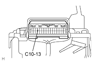
Connect an oscilloscope to terminals C10-13 and the body ground.
Start the engine.
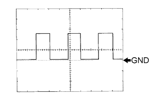 |
Check the signal waveform according to the condition(s) in the table below.
| Item | Condition |
| Tool setting | 5 V/DIV., 20 msec./DIV. |
| Vehicle condition | Driving at approx. 20 km/h (12 mph) |
| 3. CHECK FUEL RECEIVER GAUGE |
 |
Disconnect the F14 sender gauge connector.
Turn the power switch ON (IG), then check the position of the receiver gauge segment.
| Condition | Display |
| Before disconnecting connector, 1 segment is blinking | Segment blinks for 60 seconds, then changes to a different blinking cycle |
| Before disconnecting connector, other than 1 blinking segment is displayed | Current display continues for 60 seconds, then begins blinking |
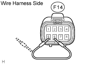
Connect terminals 5 and 6 on the wire harness side connector of the fuel sender gauge.
Turn the power switch to the ON (IG), then check the position of the receiver gauge segment.
| Condition | Display |
| Before disconnecting connector, all 10 segments are displayed | All 10 segments illuminate for 60 seconds, then begin blinking |
| Before disconnecting connector, less than 10 segments are displayed | Gauge increases to 9 segments, then begins blinking after 60 seconds |
| 4. CHECK FUEL LEVEL WARNING |
Disconnect the connector from the sender gauge.
Turn the power switch ON (IG), check that the fuel level needle indicates EMPTY and fuel level warning light comes on.
| 5. CHECK LOW OIL PRESSURE WARNING LIGHT |
Disconnect the connector from the low oil pressure switch.
Turn the power switch ON (IG).
Ground the terminal of the wire harness side connector, then check the low oil pressure warning light.
| 6. CHECK BRAKE WARNING LIGHT |
Inspect the parking brake warning light.
Disconnect the connector from the parking brake switch.
Turn the power switch ON (IG).
Ground the terminal of the wire harness side connector, then check the parking brake warning light.
Inspect the brake fluid level warning light.
Disconnect the connector from the brake fluid level warning switch.
Turn the power switch ON (IG).
Connect a terminal to the other terminal of the wire harness side connector, then check the brake fluid level warning switch.
| 7. CHECK BRAKE FLUID LEVEL WARNING SWITCH |
Remove the reservoir tank cap and strainer.
Disconnect the connector.
Measure the resistance between the terminals.
Use a syphon, etc. to take fluid out of the reservoir tank.
Measure the resistance between the terminals.
Pour the fluid back in the reservoir tank.
Reconnect the connector.
| 8. MAINTENANCE LIQUID RESETTING PROCEDURE (U. S. A. models) |
| State | Condition | Specified State |
| Blinking | Vehicle runs 4,500 miles after previous setting | Indicator blinks for 15 seconds after power switch ON (IG) (including 3 seconds for a valve check) |
| Continuously Illuminated | Vehicle runs 5,000 miles after previous setting | Indicator is continuously illuminated after power switch ON (IG) |
Press the ODO / TRIP switch until odometer displays "ODO".
Turn the power switch OFF.
Press and hold the reset switch, and turn the power switch ON (IG).
After turning the power switch ON (IG), keep holding the reset switch for at least 5 seconds. The reset procedure is completed.
| 9. CENTERED VALUE SETTING (INCLINATION SENSOR) |
Setting procedure
Connect the connector and install the meter securely in the position shown in the illustration so that it is inclined at a 20 degree angle to the vehicle's vertical line A.
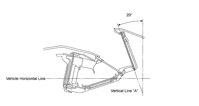
Park the vehicle on a level surface.
Turn the power switch ON (IG).
Set the odometer display into the "TRIP A" mode.
Turn the power switch OFF.
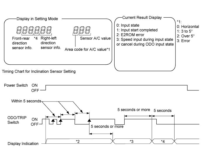
Press and hold the ODO/TRIP switch while pressing the power switch twice ON (IG). (Do not put your foot on the brake.)
Press the ODO/TRIP button (switch) 3 times within 5 seconds and hold it at least 5 seconds until the Inclination Sensor Information is displayed on the odometer.
Release the ODO/TRIP switch.
Press and hold the ODO/TRIP switch for at least 5 seconds to update the centered value. The third digit will indicate the status. The value of "1" indicates a successful reset.
Release the ODO/TRIP button. (Once the reset is complete, the odometer will returns to normal.)
Turn the power switch OFF.