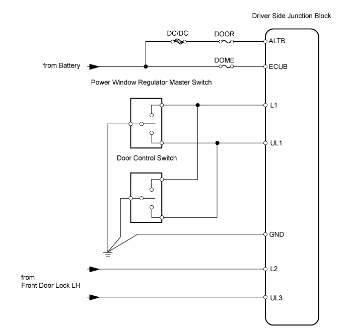
DTC B1241 Body ECU Switch Circuit Diagnosis |
| Switch Operation (ON) | Switch Operation (OFF) | Switch Condition |
| DTC is output | DTC is not output | Normal |
| DTC is output | DTC is output | Stuck ON malfunction |
| DTC is not output | DTC is not output | Contact is faulty malfunction |
| DTC No. | DTC Detection Condition | Trouble Area |
| B1241 |
|
|
| 1.INSPECT FUSE (DOOR) |
Remove the DOOR fuse from the driver side junction block.
Measure the resistance of the fuse.
|
| ||||
| OK | |
 |
| 2.READ VALUE OF TECHSTREAM (DOOR CONTROL SWITCH) |
Check the Data List for proper functioning of the door control switch.
| Tester Display | Measurement Item/Range | Normal Condition | Diagnostic Note |
| D/L SW-Lock | Door control switch lock signal / ON or OFF | ON: Door control switch is in LOCK position OFF: Door control switch is not in LOCK position | - |
| D/L SW-Unlock | Door control switch unlock signal / ON or OFF | ON: Door control switch is in UNLOCK position OFF: Door control switch is not in UNLOCK position | - |
|
| ||||
| OK | |
|
| 3.CHECK DOOR LOCK / UNLOCK FUNCTION (OPERATE VIA DRIVER SIDE DOOR KEY CYLINDER) |
Refer to "all doors lock / unlock functions do not operate via driver side door key cylinder" (Click here).
|
| ||||
| NG | ||
 | ||
| ||
| 4.INSPECT POWER WINDOW REGULATOR MASTER SWITCH (DOOR CONTROL SWITCH) |
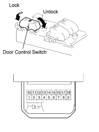 |
Measure the resistance of the switch.
| Tester Connection | Switch Condition | Specified Condition |
| 1 - 5 | Lock | Below 1 Ω |
| 1 - 8 | Unlock | |
| 1 - 5 | OFF | 10 kΩ or higher |
| 1 - 8 |
|
| ||||
| OK | |
|
| 5.CHECK WIRE HARNESS (SWITCH - ECU AND BODY GROUND) |
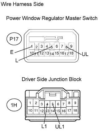 |
Disconnect the P17 switch connector.
Disconnect the 1H junction block connector.
Measure the resistance of the wire harness side connectors.
| Tester Connection | Specified Condition |
| P17-5 (L) - 1H-4 (L1) | Below 1 Ω |
| P17-8 (UL) - 1H-5 (UL1) | |
| P17-1 (E) - Body ground |
|
| ||||
| OK | |
|
| 6.CHECK DOOR CONTROL SWITCH |
Press the lock switch on the passenger side door control switch and check that all the doors lock. Press the unlock switch on the passenger side door control switch and check that all the doors unlock.
|
| ||||
| NG | |
|
| 7.INSPECT DOOR CONTROL SWITCH |
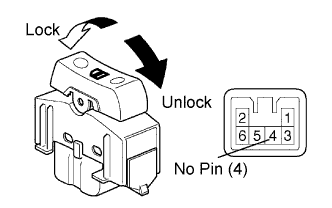 |
Measure the resistance of the switch.
| Tester Connection | Switch Condition | Specified Condition |
| 3 - 6 | Lock | Below 1 Ω |
| 3 - 5 | Unlock | |
| 3 - 6 | OFF | 10 kΩ or higher |
| 3 - 5 |
|
| ||||
| OK | |
|
| 8.CHECK WIRE HARNESS (SWITCH - ECU AND BODY GROUND) |
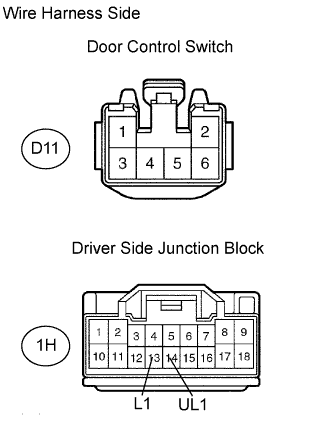 |
Disconnect the D11 switch connector.
Disconnect the 1H junction block connector.
Measure the resistance of the wire harness side connectors.
| Tester Connection | Specified Condition |
| D11-6 - 1H-13 (L1) | Below 1 Ω |
| D11-5 - 1H-14 (UL1) | |
| D11-3 - Body ground |
|
| ||||
| OK | |
|
| 9.CHECK WIRE HARNESS (DRIVER SIDE JUNCTION LOCK - BATTERY AND BODY GROUND) |
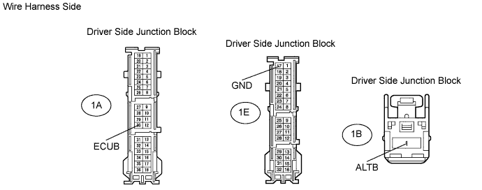
Disconnect the 1A, 1B and 1E junction block connectors.
Measure the voltage of the wire harness side connector.
| Tester Connection | Specified Condition |
| 1A-30 (ECUB) - Body ground | 10 to 14 V |
| 1B-1 (ALTB) - Body ground |
Measure the resistance of the wire harness side connector.
| Tester Connection | Specified Condition |
| 1E-17 (GND) - Body ground | Below 1 Ω |
|
| ||||
| OK | ||
| ||
| ||

